An antenna calibration certificate provides the frequency-dependent correction data needed to convert a measured receiver voltage into electromagnetic field strength. For radiated emissions testing, the most important value is usually the antenna factor (AF), together with its measurement uncertainty and calibration conditions.
A valid certificate also identifies the individual antenna, calibration method, frequency coverage, and traceability of the measurements.
These details matter because an incorrect antenna factor, missing calibration point, or unsuitable calibration method can affect EMC test results even when the antenna and EMI receiver are functioning normally.
What Does an Antenna Calibration Certificate Tell You?
An antenna calibration certificate documents measured characteristics of a specific antenna under defined conditions.
For EMC radiated emissions measurements, it commonly provides the relationship between the electromagnetic field incident on the antenna and the voltage available at its output connector.
The certificate helps engineers determine:
– Whether the antenna has valid calibration data for the required frequency range
– Which correction factors must be applied to receiver readings
– What measurement uncertainty is associated with the calibration
– Which calibration method and reference standards were used
– Whether the calibration applies to the antenna installed in the laboratory
A manufacturer’s typical antenna-factor curve is useful for product selection, but it should not automatically replace individual calibration data for formal compliance measurements.
Essential Information to Check on the Certificate
Before importing calibration data into EMC measurement software, review the certificate identification and measurement details.
| Certificate Item | Why It Matters |
|---|---|
| Manufacturer, model, and serial number | Identifies the actual antenna calibrated |
| Calibration date | Establishes when measurements were performed |
| Calibration method | Defines how antenna factors were determined |
| Frequency range | Confirms coverage of the intended measurements |
| Antenna factor table | Provides frequency-dependent corrections |
| Measurement uncertainty | Describes uncertainty associated with calibration results |
| Traceability statement | Identifies the metrological traceability basis |
| Calibration conditions | Documents relevant geometry and measurement configuration |
The serial number is particularly important in laboratories using several antennas of the same model.
Two antennas with identical model numbers may have different measured antenna factors.
Using the calibration file from another unit can introduce systematic measurement errors.
How to Read Antenna Factor Values
The antenna factor relates the incident electromagnetic field to the voltage developed at the antenna output.
For electric-field measurements, antenna factor is commonly expressed in dB/m.
The corrected field strength can be calculated using:
E (dBµV/m) = Vreceiver (dBµV) + AF (dB/m) + Cable Loss (dB) − Preamplifier Gain (dB)
This simplified equation assumes the antenna factor refers to the antenna output and the cable and preamplifier corrections are not already included.
Consider an illustrative radiated emissions measurement at 300 MHz:
| Parameter | Value |
|---|---|
| EMI receiver reading | 46.0 dBµV |
| Antenna factor | 19.0 dB/m |
| RF cable loss | 1.5 dB |
| Preamplifier gain | 15.0 dB |
| Corrected field strength | 51.5 dBµV/m |
Calculation:
46.0 + 19.0 + 1.5 − 15.0 = 51.5 dBµV/m
The numerical values are examples, not calibration data for a specific antenna.
Antenna factor must be taken from the calibration data applicable to the actual test frequency.
Incorrect correction signs or duplicated amplifier-gain compensation can produce significant errors.
Why Antenna Factor Changes with Frequency
An antenna’s response is not constant across its operating range.
Input impedance, radiation characteristics, effective length, and matching-network behavior change with frequency.
Consequently, an antenna calibration certificate normally provides multiple antenna-factor values rather than one universal correction.
For example, the 1313-3-30M6G Hybrid Antenna covers 30 MHz to 6 GHz. Its broad operating range makes frequency-dependent correction data important for accurate receiving measurements.
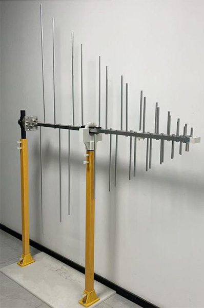
The 1313-2-80M1G Log Periodic Antenna covers 80 MHz to 1 GHz and can be used for RF emissions measurements as well as field generation.
Its gain specification is not a substitute for the antenna-factor data required when it is used as a receiving antenna.
Which Standards Apply to EMC Antenna Calibration?
Two important references are CISPR 16-1-6 and ANSI C63.5.
CISPR 16-1-6 addresses EMC antenna calibration methods for determining antenna factors, including calibration arrangements and associated measurement uncertainties.
The 2022 consolidated edition covers antenna calibration procedures across 9 kHz to 18 GHz.
ANSI C63.5-2017 provides methods for calibrating and qualifying antennas used in radiated electromagnetic interference measurements, covering 9 kHz to 40 GHz.
Depending on antenna type and application, calibration techniques may include standard-site, reference-antenna, or other specified methods.
When reviewing a certificate, confirm that the stated method is suitable for the antenna and intended EMC measurement procedure.
A certificate referencing a recognized standard does not, by itself, establish that every measurement is covered by the calibration laboratory’s accreditation.
What Does Measurement Uncertainty Mean?
Measurement uncertainty expresses the range associated with a reported calibration result under a defined level of confidence.
For example, a certificate might report:
Antenna Factor: 18.5 dB/m
Expanded Measurement Uncertainty: 1.2 dB (k = 2)
Here, k is the coverage factor. An expanded uncertainty reported with k = 2 commonly corresponds to approximately 95% coverage under the stated assumptions.
The uncertainty does not mean the antenna factor should automatically be increased or decreased by 1.2 dB during a test.
Instead, it provides information for the laboratory’s overall measurement uncertainty evaluation.
The full radiated emissions uncertainty budget may also include receiver performance, cable loss, impedance mismatch, site characteristics, antenna positioning, and measurement repeatability.
Where accreditation is required, engineers should check the calibration laboratory’s relevant ISO/IEC 17025 accreditation scope, not merely the presence of an accreditation symbol.
Free-Space Antenna Factor vs. Test-Site Performance
One common misunderstanding is that a calibrated antenna guarantees accurate measurements at any test site.
It does not.
An antenna’s response can be affected by nearby conductive structures, reflections, orientation, and its position relative to a source.
Free-space antenna factor describes antenna performance under specified calibration conditions. The actual EMC measurement environment introduces additional influences.
For example, a Standard 3m Method Anechoic Chamber must be evaluated for relevant site-performance requirements, including normalized site attenuation or site VSWR where applicable.
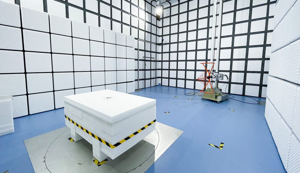
These tests assess the measurement environment rather than replacing antenna calibration.
A calibrated antenna and a validated test site are therefore complementary requirements.
Calibration Requirements for Different Antenna Types
Different EMC antennas require calibration data appropriate to their measurement function.
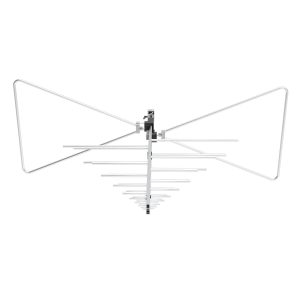
Biconical, log-periodic, and hybrid antennas are commonly used in radiated emissions measurements. Their receiving antenna factors are applied across the frequency ranges covered by the relevant calibration.
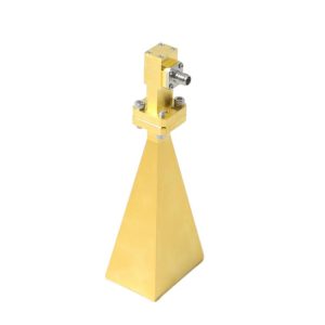
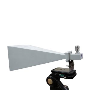
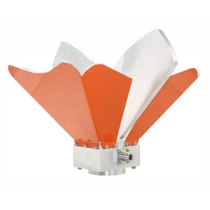
Horn antennas, such as the OBH-08180 Broadband Dual-Ridged Horn Antenna, operate at higher RF frequencies. Calibration geometry, polarization, antenna orientation, and applicable correction data should be reviewed carefully.
Loop antennas are used for low-frequency magnetic-field measurements. Their calibration must be interpreted according to the magnetic-field quantity and units stated on the certificate.
The 1313 Series Loop Antenna includes active and passive configurations covering 9 kHz to 30 MHz.

For an active loop antenna, calibration must account for the integrated electronics. Applying separate amplifier-gain correction when that gain is already included in the calibrated factor would produce an incorrect result.
Antenna calibration for receiving measurements should also be distinguished from gain and power-handling specifications used when selecting transmitting antennas for radiated immunity testing.
How to Import Antenna Calibration Data into EMC Software
Calibration data is commonly supplied as a frequency table or electronic correction file.
Before loading it into automated EMC test software:
– Confirm the antenna model and serial number.
– Check frequency units, such as MHz or GHz.
– Verify the antenna-factor units.
– Confirm the correction-factor sign convention.
– Identify whether cable or amplifier corrections are included.
– Check interpolation settings between calibrated frequencies.
– Confirm the frequency range covered by valid data.
Do not extrapolate correction factors beyond the calibrated frequency range without technical justification.
After import, compare several software correction values against the original certificate.
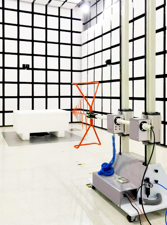
In automated radiated emissions systems, antenna positioning also matters. The GEAM-4600 Antenna Mast System supports controlled antenna-height and polarization adjustments, but positioning repeatability cannot compensate for incorrect calibration data.
When Should an EMC Antenna Be Recalibrated?
There is no single recalibration interval suitable for every antenna and laboratory.
The interval should consider applicable quality requirements, measurement history, usage, environmental exposure, and manufacturer recommendations.
Recalibration should be considered after:
– Mechanical damage or accidental dropping
– Bent antenna elements or damaged connectors
– Repairs affecting electrical performance
– Significant changes in antenna response
– Suspected calibration-data discrepancies
– Expiration of the laboratory’s assigned calibration interval
Antenna condition checks between calibrations can help identify unexpected changes.
Comparing current performance against previous calibration data is particularly useful for identifying drift or damage, although such comparisons do not replace formal recalibration where required.
Antenna Calibration Certificate Review Checklist
Before using an antenna for formal EMC measurements, verify that:
– The certificate matches the actual antenna serial number.
– The required measurement frequencies are covered.
– The calibration method is appropriate.
– The antenna-factor values and units are understood.
– Measurement uncertainty is documented.
– Metrological traceability and accreditation requirements are satisfied.
– Calibration files match the original certificate.
– Cable and preamplifier corrections are not duplicated.
– The antenna is mechanically undamaged.
– The laboratory’s calibration interval and equipment records are current.
An antenna calibration certificate is most useful when its data is correctly integrated into the complete measurement chain. The certificate establishes calibrated antenna characteristics; the receiver, cables, antenna positioning, and EMC test site must still be managed to obtain reliable radiated emissions results.