Anechoic Chamber Introduction
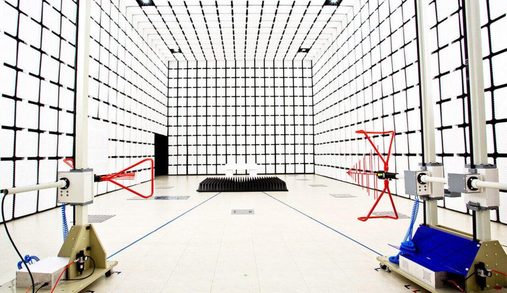
The Standard 3m Method Anechoic Chamber is designed for electromagnetic compatibility (EMC) testing of small and medium-sized electronic equipment, including radiated emissions (RE) and radiated immunity (RI) testing.
With a 3-meter test distance, the chamber provides a practical solution for EMC laboratories seeking to balance measurement requirements, equipment size, and available installation space.
The system integrates RF shielding, absorbing materials, antenna positioning equipment, and a turntable. Chamber dimensions, frequency coverage, quiet zone requirements, and site validation criteria can be configured according to the equipment under test (EUT) and applicable EMC standards.


Key Structural Parameters
| Test Distance | 3m (EUT to antenna) |
|---|---|
| Internal Dimensions | Length: ~9m (meets test distance and quiet zone requirements) Width: ~6m (ensures quiet zone integrity) Height: ~6m (accommodates antenna movement and quiet zone) |
| Absorbing Materials | Walls/Ceiling: Carbon-loaded pyramidal/foam absorbers (0.3–0.45m height), covering 30 MHz–18 GHz (extendable to 40 GHz) Floor: Metallic ground plane (galvanized steel/aluminum), per CISPR 16-1-4 |
| Shielded Door | Double-layer design, ≥100 dB shielding (30 MHz–18 GHz; optional 40 GHz) |
Typical Applications of a 3m Anechoic Chamber
A 3m EMC anechoic chamber is commonly used for testing electronic products that can be accommodated within the required test volume.
Typical applications include:
– Consumer Electronics: Radiated emissions testing for computers, displays, and other electronic devices.
– Industrial Electronics: EMC evaluation of control units, electronic modules, and compact industrial equipment.
– Radiated Immunity Testing: RF electromagnetic field immunity testing where the chamber configuration meets the applicable test requirements.
– EMC Laboratory Development: Test facilities requiring a 3m measurement distance, controlled antenna positioning, and a validated test environment.
The suitability of a 3m chamber depends on EUT dimensions, cable arrangements, applicable standards, and the required frequency range.
Critical Performance Metrics
| Shielding Effectiveness | Low Frequency (14 kHz–1 MHz): ≥80 dB High Frequency (1 MHz–18 GHz): ≥100 dB (typical 120 dB) |
|---|---|
| Grounding Resistance | Standard: IEC 60364-6 (GB/T 16895.23) Requirement: ≤ 4Ω |
| Insulation Resistance | Standard: IEC 60364-6 (GB/T 16895.23) Requirement: ≤ 2 MΩ |
| Quiet Zone | Dimensions: Approximately 1.5 meters or 2 meters in diameter and height (at 3 meters from the antenna) |
| Normalized Site Attenuation (NSA) | Compliance Standards: CISPR 16-1-4 (GB/T 6113.104), ANSI C63.4 Deviation: Within ±4 dB (30 MHz–1 GHz) |
| Site Voltage Standing Wave Ratio (SVSWR) | Compliance Standards: CISPR 16-1-4 (GB/T 6113.104), ANSI C63.4 Requirement: ≤ 6 dB |
| Field Uniformity | Applicable Standard: IEC 61000-4-3 (GB/T 17626.3, applicable only for radiated immunity testing) Uniform Area: Field strength variation ≤ 6 dB within a 1.5m × 1.5m area (80 MHz–6 GHz) |
| Influence Assessment of Radiated Emission Test Table | Compliance Standards: CISPR 16-1-4, ANSI C63.4 Requirement: The influence assessment results of the radiated emission test table must be incorporated into the uncertainty evaluation of radiated emission measurements |
| Ambient Noise Level | At least 6 dB below the EMC product standard limits |
Antenna & Turntable System
| Antenna Types | Dual-polarized (>30 MHz), 9 kHz–40 GHz coverage |
|---|---|
| Turntable | Diameter: 2–3m, 500 kg–1 ton/m² load capacity Accuracy: ±1° |
| Antenna Tower | 1–4m height adjustment, ±0.5 cm precision |
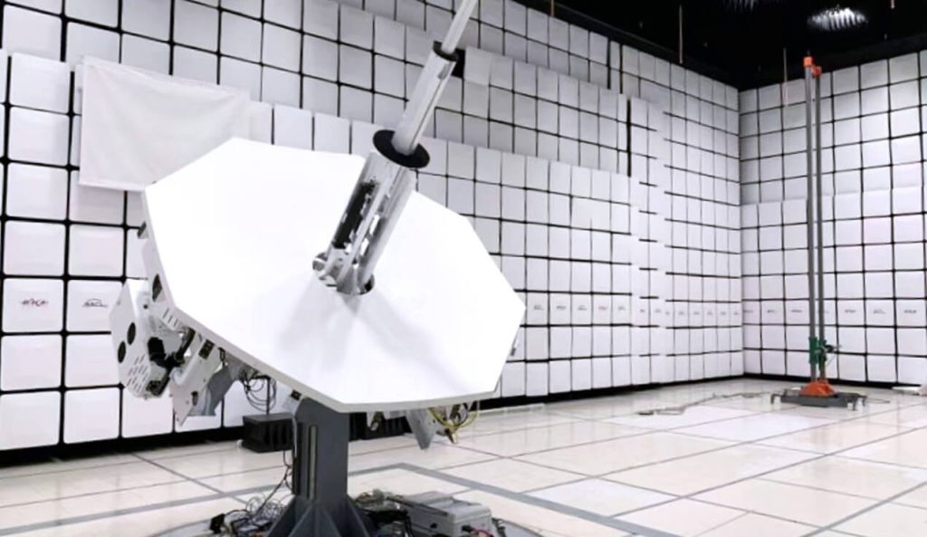
For automated EMC measurements, the chamber can be integrated with an antenna mast, turntable, and positioning controller. GE EMC offers the GETT-2000 Turntable System and GEAM-4600 Antenna Mast System for controlled EUT rotation, antenna height adjustment, and polarization switching.
Positioning equipment should be selected according to the chamber layout, EUT dimensions, loading requirements, and test procedures.
Compliance Standards
| Radiated Emissions | CISPR 32 (GB/T 9254.1), FCC Part 15, EN 55032 |
|---|---|
| Radiated Immunity | CISPR 35 (GB/T 9254.2), EN 55032 |
Auxiliary Systems
| Power Supply & Filtering | Power: Independent filtered power supply system providing clean power Signal line filtering: All feedthrough interfaces shall be equipped with RF filters |
|---|---|
| Environmental Control | Temperature: 20~25℃ (±2℃) Humidity: 30%~70% RH (anti-condensation) |
| Safety Systems | Emergency stop button, smoke alarm, fire suppression system RF radiation safety monitoring (compliant with occupational health standards) |
When Should You Choose a 3m Anechoic Chamber?
A 3m anechoic chamber is often suitable for laboratories testing small and medium-sized electronic products where a 3-meter measurement distance meets the applicable test requirements.
For larger EUTs, complex cable arrangements, or increased test volume requirements, a 5m or 10m chamber may be considered. A longer measurement distance does not automatically provide better measurement accuracy; site validation, chamber geometry, and antenna positioning must also be evaluated.
For a detailed comparison, see our Guide to Selecting 3m, 5m and 10m Anechoic Chambers.
What is a 3m anechoic chamber used for?
A 3m anechoic chamber provides a controlled EMC testing environment for radiated emissions and, when appropriately configured, radiated immunity testing. It is commonly used for small and medium-sized electronic equipment.
What is the difference between a 3m and 10m anechoic chamber?
The main difference is the nominal measurement distance. A 10m chamber generally requires more installation space and can accommodate larger test arrangements. The appropriate chamber depends on EUT dimensions, applicable standards, and site validation requirements.
What information is needed for a 3m chamber quotation?
Customers should provide the EUT dimensions and weight, required test frequency range, applicable EMC standards, radiated emissions or immunity requirements, and available installation space. These details help determine the appropriate chamber configuration and supporting equipment.
Request a 3m Anechoic Chamber Quotation
Planning a 3m EMC anechoic chamber for your laboratory? Share your testing requirements, EUT dimensions, frequency range, and available installation space with our team.
We can help review the chamber configuration, positioning equipment, and project requirements.