In this article, EMC chamber testing refers to EMC tests performed on equipment inside an anechoic or semi-anechoic chamber, particularly radiated emissions and radiated immunity testing.
It should be distinguished from EMC chamber validation, where the chamber itself is evaluated using parameters such as Normalized Site Attenuation (NSA), SVSWR, shielding effectiveness, and field uniformity.
For EUT testing, the chamber provides a controlled electromagnetic environment where external RF interference is reduced and internal reflections are managed. The chamber works together with antennas, an EUT turntable, antenna positioning equipment, RF cables, EMI receivers, RF power amplifiers, field probes, and test software.
The two main chamber-based tests covered here are:
– Radiated emissions testing — measuring unwanted RF energy generated by the EUT.
– Radiated immunity testing — exposing the EUT to a controlled RF field and monitoring its performance.
What the EMC Chamber Does During Testing
An ordinary laboratory room contains many uncontrolled RF sources and reflective surfaces.
Mobile networks, Wi-Fi, radio transmitters, electrical equipment, metal walls, floors, and furniture can all affect RF measurements.
An EMC chamber solves two major problems.
First, the conductive enclosure provides electromagnetic shielding, reducing interference between the test environment and the outside world.
Second, RF absorbing materials reduce unwanted reflections inside the room.
A standard semi-anechoic chamber normally uses absorbers on the walls and ceiling while retaining a conductive ground plane.
A Fully Anechoic Chamber (FAR) also uses absorber on the floor.
The correct chamber configuration depends on the applicable test standard, test distance, frequency range, and EUT size.

EUT Setup Comes Before the Measurement
A repeatable chamber test starts with a controlled EUT setup.
The laboratory should define:
– EUT operating mode
– Power supply configuration
– Peripheral equipment
– Communication activity
– Loads and simulators
– Cable length and routing
– Software condition
– Test distance
– EUT orientation
The objective is normally to operate the product in a representative condition that can produce relevant emissions or expose important functions during immunity testing.
Cable arrangement is especially important.
Power, Ethernet, signal, and communication cables can behave as RF radiating structures. Moving a cable between two tests may therefore change the measured emissions even when the electronics remain unchanged.
For compliance measurements, the physical configuration should be documented so it can be reproduced.
How Radiated Emissions Testing Works
Radiated emissions testing determines how much electromagnetic energy escapes from the EUT.
A typical measurement chain is:
EUT → Receiving Antenna → RF Cable / Preamplifier → EMI Receiver
The antenna converts the electromagnetic field into an RF signal that can be measured by the EMI receiver.
The raw receiver level is then corrected using factors such as:
– Antenna factor
– RF cable loss
– Preamplifier gain
– Other calibrated RF path losses
The resulting field strength is compared with the applicable radiated emissions limit.
However, the test is not performed at only one EUT orientation.
Electronic equipment normally produces a directional radiation pattern, so the measurement system must search for the highest emission.
Why the EUT Is Rotated
Different parts of an electronic product can radiate in different directions.
Typical sources include:
– PCB traces
– Digital clocks
– Enclosure seams
– Ventilation openings
– Power converters
– External cables
– Communication interfaces
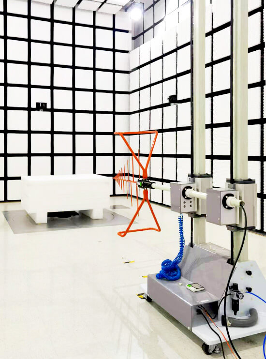
The EUT is therefore placed on a turntable and rotated through the required angular range.
At one frequency, the maximum emission may appear when the front of the product faces the antenna. At another frequency, the strongest radiation may occur at an intermediate angle.
The EMC positioning system allows the turntable angle to be controlled and recorded so the system can return to a previously detected maximum.
This is particularly useful during EMC troubleshooting, where a failed frequency must be measured again after a design modification.
Why Antenna Height and Polarization Change
In a semi-anechoic chamber, the receiving antenna detects both the direct signal from the EUT and energy reflected from the conductive ground plane.
As antenna height changes, the relative path length and phase of these signals also change.
The received level may therefore increase or decrease significantly with height.
For many conventional radiated emissions tests, the antenna is vertically scanned to locate the maximum received signal.
The antenna is also evaluated in both:
– Horizontal polarization
– Vertical polarization
The strongest result is determined by the orientation of the radiating structure.
The measurement process therefore searches for the combination of:
Frequency + EUT Angle + Antenna Height + Polarization
that produces the maximum emission.
This process is covered in more detail in Why EUT Rotation and Antenna Height Scanning Matter in Radiated Emission Testing.
Pre-Scan and Final Measurement
A complete radiated emissions test does not normally use the slowest detector at every frequency from the beginning.
A more practical workflow is:
Pre-Scan
A relatively fast sweep identifies important emission peaks.
Maximization
The system checks selected frequencies while adjusting turntable angle, antenna height, and polarization.
Final Measurement
The antenna and EUT return to the recorded worst-case positions and the required final detector measurement is performed.
This approach reduces test time while still identifying the maximum radiated emission.
Automated turntables and antenna masts make this process faster and more repeatable.
How Radiated Immunity Testing Works
Radiated immunity testing reverses the direction of the RF energy.
Instead of measuring electromagnetic energy generated by the EUT, the test system deliberately creates an RF field around it.
A typical signal path is:
RF Signal Generator → RF Power Amplifier → Transmitting Antenna → EUT
The signal generator produces the required RF frequency and modulation.
The RF power amplifier increases the signal to the power level needed to generate the specified electric field.
The transmitting antenna converts this RF power into electromagnetic energy.
The EUT is then monitored while the test frequency is swept through the required range.
The IEC 61000-4-3 Radiated Immunity Test Overview explains the typical test configuration and field requirements in more detail.
Field Calibration Is Required Before Immunity Testing
Amplifier output power does not directly equal field strength.
The actual electric field depends on:
– Amplifier output
– Antenna gain
– Test distance
– RF cable loss
– Antenna VSWR
– Chamber reflections
– Frequency
– Antenna position
Before the EUT test begins, a calibrated field probe is used to characterize the test area.
The system determines how much RF power is required at each frequency to generate the required field.
These values are stored as calibration data and used during the actual immunity sweep.
This is why a 100 W amplifier, for example, does not automatically mean that a certain V/m field can be achieved across the entire test range.
The relationship between these parameters is discussed in How Amplifier Power, Antenna Gain, and Test Distance Determine Field Strength.
What Is Monitored During Radiated Immunity Testing
The objective of an immunity test is not simply to create an RF field.
The EUT must be monitored continuously to determine whether its operation is affected.
Depending on the product, engineers may monitor:
– Communication
– Display output
– Sensor readings
– Motor operation
– Control signals
– Output voltage
– Data transmission
– Error codes
– Reset events
– Safety-related functions
A failure does not always mean complete shutdown.
Temporary communication loss, incorrect data, degraded operation, unintended reset, or failure to recover can all be relevant depending on the applicable performance criteria.
Antennas Serve Different Roles in Emissions and Immunity Testing
The antenna may look similar in both test setups, but the important specifications change.
For radiated emissions, the antenna is used as a receiver. Important parameters include:
– Antenna factor
– Sensitivity
– Calibration
– Frequency range
For radiated immunity, the antenna is used as a transmitter. Important parameters include:
– Antenna gain
– VSWR
– Power handling
– Beamwidth
– Frequency range
For example, the 1313-2-80M1G log-periodic antenna covers a broad VHF/UHF range and can be used in EMC applications requiring broadband antenna performance.
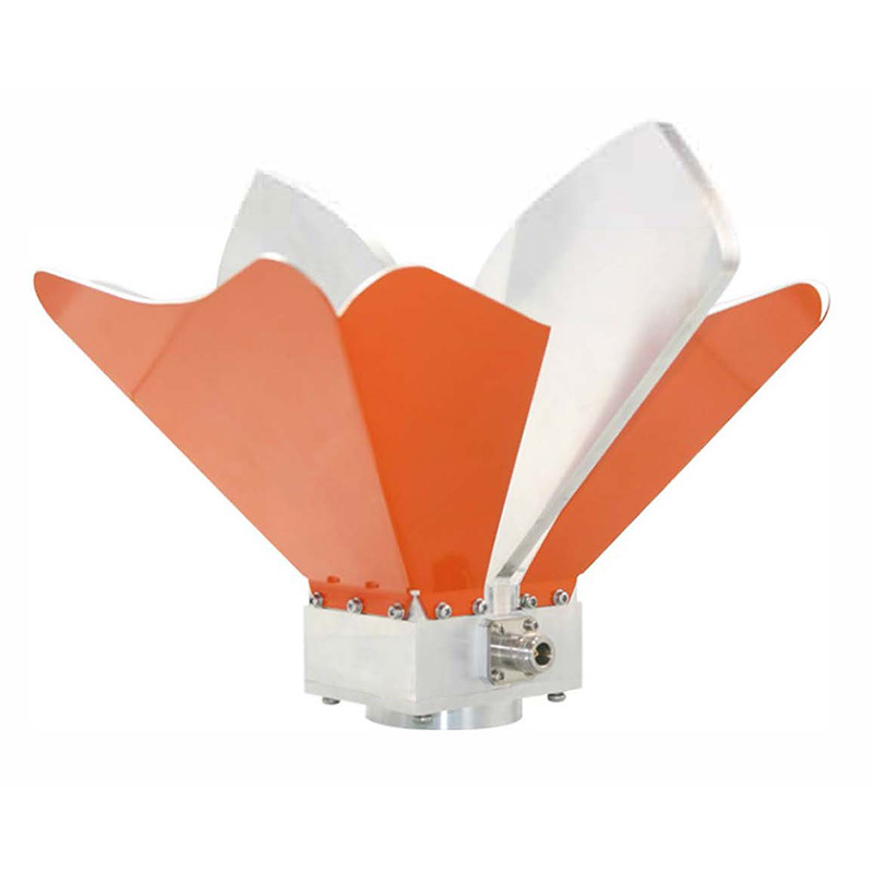
At higher frequencies, a OBH-08180 broadband dual-ridged horn antenna provides directional broadband coverage for microwave EMC testing.
Selecting the correct antenna affects both measurement sensitivity and the amount of RF amplifier power needed during immunity testing.
The Measurement Chain Must Be Controlled
Even inside a good EMC chamber, incorrect measurement-chain data can produce inaccurate results.
For radiated emissions, check:
– Antenna calibration
– Cable-loss correction
– Preamplifier gain
– Connector condition
– EMI receiver settings
For radiated immunity, check:
– RF amplifier output
– Cable and switch loss
– Antenna gain
– Reflected power
– Field-probe calibration
The complete EMC measurement system should be treated as one calibrated signal chain.
Changing one RF cable, antenna, amplifier, or preamplifier may require updated correction or calibration data.
Chamber Validation Is a Prerequisite, Not the EUT Test
The chamber itself must be validated before it is relied upon for compliance testing.
Typical chamber performance checks include:
– Shielding effectiveness
– Background noise
– Normalized Site Attenuation (NSA)
– SVSWR
– Field uniformity
These tests confirm that the chamber provides a suitable electromagnetic environment.
They should not be confused with the emissions or immunity tests being performed on the EUT.
For a detailed explanation of these chamber-performance measurements, see Key Anechoic Chamber Performance Indicators: NSA, SVSWR, and Field Uniformity.
Practical EMC Chamber Testing Workflow
A typical EUT test inside an EMC chamber can be summarized as:
Confirm Standard → Configure EUT → Verify Measurement Setup → Position EUT and Antenna → Perform Pre-Scan or Field Calibration → Run Required EMC Test → Identify Worst-Case Conditions → Record Results
Before testing, confirm:
– Applicable EMC standard
– Required test method
– Frequency range
– Test distance
– EUT operating mode
– Cable configuration
– Antenna type
– Turntable position
– Antenna height and polarization
– Instrument calibration
– Correction data
– EUT monitoring method
The chamber provides the controlled RF environment, but reliable EMC chamber testing depends on the complete combination of EUT setup, antenna positioning, calibrated RF equipment, measurement procedures, and repeatable test conditions.