

Accurate EMC antenna measurements depend on more than the antenna specification printed on a datasheet. A calibrated antenna can still produce inconsistent radiated emissions results if the antenna factor is applied incorrectly, the RF cable has changed, the antenna is positioned at the wrong height, or the test site contains uncontrolled reflections.
In practical EMC testing, the antenna operates as part of a complete measurement chain that includes the equipment under test, antenna mast, turntable, coaxial cable, preamplifier, EMI receiver, chamber, test software, and correction data.
A measurement problem in any part of this chain can change the final field-strength result. This is why EMC antenna measurement accuracy should be evaluated at system level rather than by checking the antenna alone.
Antenna Calibration and Antenna Factor
Antenna factor is one of the main correction values used in radiated emissions testing. It describes the relationship between the electric field incident on the antenna and the voltage produced at the antenna output.
The basic field-strength calculation is:
Field Strength = Receiver Reading + Antenna Factor + Cable Loss − Preamplifier Gain
If the antenna factor or cable-loss value is incorrect, the final radiated emissions result will also be incorrect even when the EMI receiver reading is stable.
The calibration file should correspond to the exact antenna used in the test. It should not be replaced by a generic curve from another antenna of the same model.
Small differences can result from:
* Antenna element dimensions
* Balun response
* Connector condition
* Manufacturing tolerances
* Mechanical damage
* Previous repairs
* Aging and environmental exposure
The calibration data should identify the antenna serial number, calibration frequency points, polarization, measurement distance, calibration method, and measurement uncertainty.
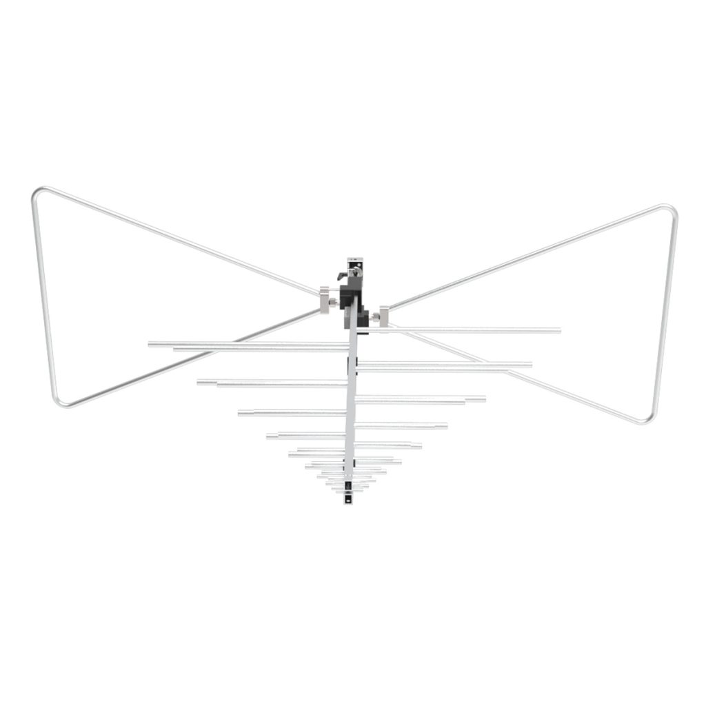
The OLP-00330 log-periodic antenna covers 30 MHz to 3 GHz and is individually calibrated. Using the supplied frequency-dependent calibration data is more accurate than applying one nominal antenna factor across the complete range.
More information about the relationship between antenna factor, frequency range, VSWR, and power handling is available in How Frequency Range, Antenna Factor, VSWR, and Power Handling Affect EMC Antenna Selection.
Calibration Frequency Resolution
A broadband EMC antenna may operate across several gigahertz, but its antenna factor does not change uniformly with frequency.
If the calibration points are spaced too widely, the test software must interpolate across large frequency intervals. This can hide narrow changes in antenna response, particularly near:
* The lower operating-frequency limit
* Element transition regions
* Resonant frequencies
* Impedance-matching variations
* The crossover between different antenna structures
Calibration frequency resolution should be suitable for the antenna type and intended measurement range.
A hybrid or log-periodic antenna covering 30 MHz to several gigahertz requires more detailed correction data than a narrowband antenna used over a limited range.
The calibration interval should also be checked when importing antenna data into EMC test software. Incorrect frequency units, missing points, duplicated frequencies, or shifted columns can introduce errors that are not immediately visible during testing.
RF Cable Loss and Cable Condition
The coaxial cable between the antenna and EMI receiver introduces frequency-dependent insertion loss.
Cable loss generally increases with frequency. A cable that introduces limited loss at 100 MHz may produce significantly greater attenuation at several gigahertz.
This loss must be added to the measured receiver level when calculating the electric field strength.
The cable-loss file should correspond to:
* The actual cable used
* The complete cable length
* Installed connectors and adapters
* The current cable condition
* The measurement frequency range
Using the correction data from another cable of the same type is not sufficient for accurate EMC measurements.
Cable performance can change because of:
* Repeated bending
* Tight bending radius
* Connector wear
* Loose connector torque
* Internal conductor damage
* Moisture or contamination
* Cable movement during antenna-height scans
At higher frequencies, even small changes in cable routing can affect insertion loss and phase response.
The RF cable should be supported so that it does not pull on the antenna, change antenna alignment, or form an uncontrolled loop as the antenna mast moves.
Cable-loss verification should be repeated after connector replacement, mechanical damage, or any significant change to the installed cable path.
Antenna Height and Positioning Accuracy
In a semi-anechoic chamber or open-area test site, radiated emissions results can change with antenna height because the direct signal and the signal reflected from the ground plane combine at the receiving antenna.
At one height, the signals may reinforce each other. At another height, they may partially cancel.
This is why many radiated emissions procedures require the antenna to scan through a defined height range while the system searches for the maximum signal level.
If the antenna mast does not return to the same height accurately, repeated measurements may produce different results.
Positioning errors may come from:
* Mechanical backlash
* Incorrect mast zero position
* Drive-belt or chain wear
* Antenna adapter dimensions
* Cable tension
* Mast deflection under antenna weight
* Incorrect software position feedback
The relevant height is normally the antenna reference point or centerline, not simply the position displayed for the mast carriage.
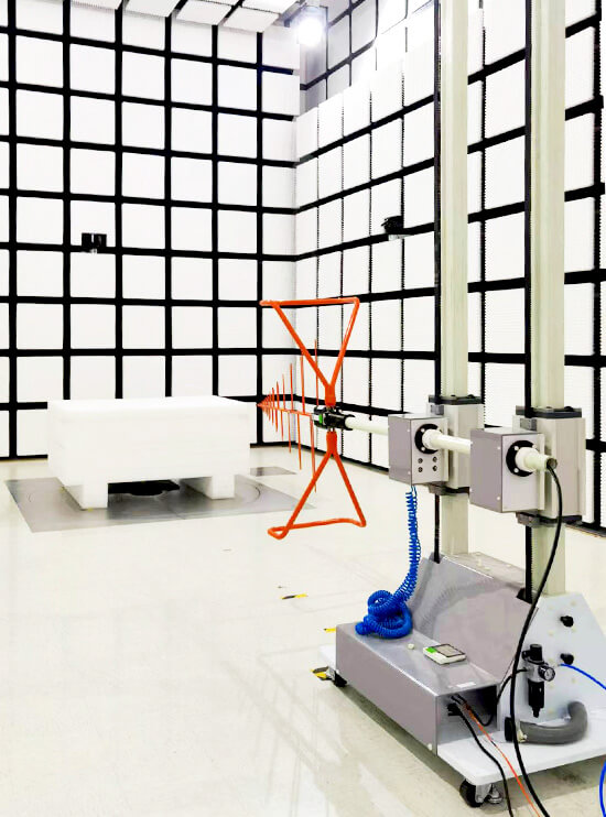
The anechoic chamber positioning system integrates antenna-height movement, polarization switching, EUT rotation, and controller communication. Coordinated positioning reduces operator-dependent variation and allows the system to return to the recorded maximum position.
A more detailed discussion is available in Antenna Positioning Accuracy and Its Impact on EMC Test Results.
Antenna-to-EUT Distance
The distance between the antenna and the equipment under test directly affects measured field strength.
Radiated emissions testing may use a 3 m, 5 m, or 10 m measurement distance depending on the applicable standard, EUT size, chamber design, and available test facility.
The distance must be measured from the correct antenna reference point to the specified EUT boundary or reference point.
Common distance errors include:
* Measuring from the antenna support instead of the antenna reference point
* Ignoring the depth of a large antenna
* Incorrectly positioning an irregularly shaped EUT
* Allowing the EUT to move away from the rotation center
* Changing antenna tilt without checking the reference distance
An off-center EUT can change its distance from the antenna as the turntable rotates. This introduces an additional variation that may be incorrectly attributed to EUT radiation pattern.
The turntable center, EUT position, antenna reference point, and chamber test distance should be checked together before the scan begins.
Horizontal and Vertical Polarization
Radiated emissions measurements normally require both horizontal and vertical antenna polarization.
The measured level depends on how the radiating structure inside the EUT is aligned with the receiving antenna.
A vertical cable may produce a higher reading in vertical polarization, while a horizontal enclosure opening or PCB trace may couple more strongly to a horizontally polarized antenna.
Measurement accuracy can be affected when:
* The antenna is not rotated through a complete 90 degrees
* The polarization mechanism has mechanical play
* The antenna shifts position during polarization switching
* The RF cable changes shape between orientations
* The antenna boresight moves away from the EUT
Automatic polarization switching improves repeatability, but the mechanism still needs periodic verification.
The antenna should remain aligned with the EUT after every polarization change. A correct polarization setting with incorrect boresight can still produce a lower measured signal.
Antenna Boresight and Directional Radiation
Directional EMC antennas, including log-periodic and dual-ridged horn antennas, must point toward the EUT.
The effect becomes more significant at higher frequencies, where antenna beamwidth may become narrower and the EUT radiation pattern may contain sharper directional maxima.
Incorrect boresight can result from:
* Antenna mast tilt error
* Incorrect mounting bracket
* Antenna sag
* Cable weight
* Misaligned polarization mechanism
* Failure to adjust tilt during height scanning
For high-frequency radiated emissions testing, a small angular error may reduce the received signal enough to change the measured margin to the limit.
The article Applications of Dual-Ridged Horn Antennas in EMC Testing explains how gain, beamwidth, antenna alignment, and test distance affect measurements above 1 GHz.
Chamber Reflections and Site Performance
An EMC antenna measures both the direct signal from the EUT and any reflected signals that reach the antenna.
Reflections may come from:
* Chamber walls
* Floor or ground plane
* Shielded door
* Turntable
* Antenna mast
* Lighting equipment
* Cable trays
* Monitoring cameras
* Support tables
* Conductive fixtures
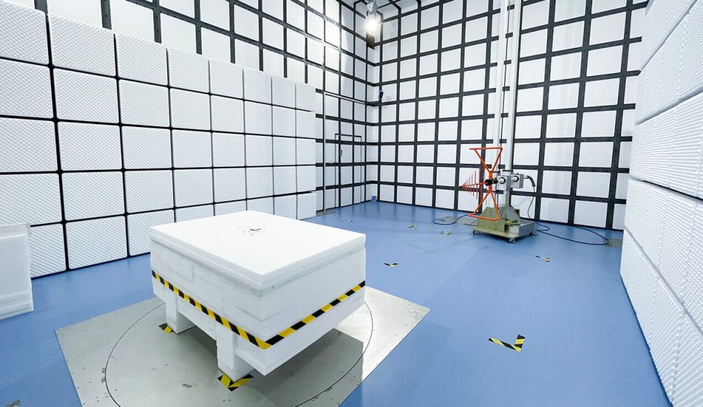
Anechoic chamber absorbers are designed to reduce these reflections, but absorber performance varies with frequency, material type, thickness, and installation quality.
Damaged absorbers, exposed conductive areas, incorrect absorber layout, or additional equipment placed inside the chamber can change site performance.
A standard 3 m anechoic chamber must provide a controlled test distance, suitable quiet zone, low ambient noise, and compliant antenna and turntable positioning.
Chamber validation and routine site checks should be treated separately from antenna calibration. A calibrated antenna cannot correct a test site with excessive reflections.
Background Noise and System Noise Floor
The measurement system must distinguish EUT emissions from the background noise generated by the chamber, receiver, preamplifier, cables, and surrounding environment.
Common background sources include:
* Radio and television signals
* Cellular base stations
* Wi-Fi transmitters
* Chamber lighting
* Turntable motors
* Antenna mast drives
* Monitoring equipment
* Computers and displays
* Power supplies
* Signals entering through unfiltered cables
A background scan should be performed with the EUT switched off while the rest of the measurement setup remains unchanged.
If the background level is close to the EUT signal, the measurement may not accurately represent the EUT emission.
A preamplifier can improve the system noise floor, but excessive gain may overload the EMI receiver when strong signals are present.
The preamplifier should be checked for:
* Frequency response
* Gain calibration
* Noise figure
* Compression
* Maximum input level
* Power supply stability
The complete measurement path is described in How EMC Measurement System Works.
EMI Receiver Settings
Incorrect EMI receiver settings can produce measurement errors even when the antenna setup is correct.
Important settings include:
* Frequency range
* Resolution bandwidth
* Detector type
* Sweep time
* Dwell time
* Input attenuation
* Preamplifier state
* Frequency step size
* Transducer correction file
Peak detection is normally used during a fast pre-scan, while quasi-peak, average, or other detectors may be required for final measurements.
If the sweep is too fast, the receiver may not capture intermittent or narrowband disturbances accurately. If the dwell time is too short, the measured level may not represent the maximum emission.
The receiver settings must follow the applicable standard and remain synchronized with turntable rotation and antenna-height movement.
EUT Position and Cable Arrangement
The antenna can only produce repeatable results when the EUT setup is also repeatable.
External cables are often major radiating structures. Their height, length, routing, termination, and distance from the ground plane can significantly affect the measured emission.
The EUT setup should control:
* Product orientation
* Cable length and routing
* Cable height above the ground plane
* Auxiliary equipment position
* Power supply arrangement
* Operating mode
* Load condition
* Communication activity
* Support-table material
Photographs and setup diagrams are useful for reproducing a test later.
The EUT should remain within the chamber quiet zone throughout turntable rotation. Cables should not tighten, drag, or change position as the platform moves.
Connector and Adapter Integrity
Every connector and RF adapter in the measurement chain introduces loss and potential mismatch.
Loose, dirty, damaged, or incorrectly torqued connectors can cause unstable readings. This is particularly important above 1 GHz, where small mechanical defects can produce noticeable changes in RF performance.
Before testing, inspect:
* Antenna connector
* RF cable connectors
* Adapters
* Preamplifier input and output
* EMI receiver input
* Bulkhead feedthroughs
Unnecessary adapters should be removed where possible. When an adapter is required, its insertion loss should be included in the correction data.
Connectors should not be tightened by rotating the antenna or cable body. This can damage the internal cable structure or antenna feed.
Measurement Repeatability Checks
A practical repeatability check can identify setup problems before formal measurements begin.
The laboratory can select one or more stable EUT emission frequencies and repeat the measurement after:
* Moving and returning the antenna
* Changing polarization
* Rotating and returning the turntable
* Reconnecting the RF cable
* Restarting the measurement software
Large changes indicate that the test system may contain a mechanical, electrical, or procedural problem.
Repeatability checks are particularly useful after:
* Antenna calibration
* Cable replacement
* Mast maintenance
* Turntable repair
* Chamber modification
* Software updates
* Receiver or preamplifier replacement
Practical Pre-Test Checklist
Before starting a radiated emissions measurement, confirm:
* The correct antenna and serial-number calibration file are selected.
* Antenna calibration is still valid.
* RF cable-loss data matches the installed cable.
* Connectors and adapters are clean and secure.
* Antenna height reference is correct.
* Horizontal and vertical polarization operate properly.
* Antenna boresight is directed toward the EUT.
* Antenna-to-EUT distance has been verified.
* The EUT is centered on the turntable.
* EUT cables follow the required arrangement.
* Chamber background noise is sufficiently low.
* Receiver detector and bandwidth settings are correct.
* Preamplifier gain and compression limits are understood.
* Turntable and antenna mast positions are repeatable.
* The complete setup is documented before final measurement.










