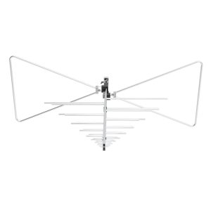
Conducted disturbance power testing is an EMC measurement method used to evaluate radio-frequency interference associated with the cables connected to electrical and electronic equipment.
Unlike conventional conducted emission measurements using a Line Impedance Stabilization Network (LISN), this method uses an absorbing clamp that moves along the cable under test to identify the position producing the maximum disturbance power.
The method is particularly relevant to household appliances, electric tools, and similar equipment tested under applicable CISPR 14-1 requirements.
A complete conducted disturbance power test system combines an absorbing clamp, a positioning rail, an EMI receiver, a controller, and a properly arranged test site.
Correct cable positioning, clamp movement, calibration, and electromagnetic isolation are essential for repeatable measurements.
What Is Conducted Disturbance Power Testing?
Electrical equipment can generate high-frequency interference through switching circuits, motors, electronic controllers, and power conversion components.
Part of this interference propagates along connected power or signal cables as common-mode RF current.
These cables can then act as radiating structures, contributing to electromagnetic interference.
Conducted disturbance power testing evaluates the RF disturbance associated with these cables using a calibrated absorbing clamp.
The measurement principle is defined in CISPR 16-2-2, which covers absorbing clamp disturbance power measurements from 30 MHz to 1 GHz.
For household appliances, electric tools, and similar equipment, CISPR 14-1 specifies disturbance power testing in the 30 MHz to 300 MHz range where the method is applicable.
The applicable product standard determines the actual measurement range, limits, and test configuration.
Main Equipment Required
A typical conducted disturbance power measurement setup includes:
– Equipment Under Test (EUT)
– Absorbing clamp
– Conducted disturbance power test rail
– EMI receiver or compliant spectrum analyzer
– RF measurement cable
– Positioning controller
– EMC measurement software
– Non-metallic EUT support
– Suitable test site with controlled electromagnetic conditions
The basic signal path is:
EUT Cable → Absorbing Clamp → RF Cable → EMI Receiver
The positioning system moves the absorbing clamp along the cable while the receiver measures the disturbance signal.
Unlike an RF power amplifier, the absorbing clamp does not inject a disturbance into the EUT. It measures interference already generated by the equipment.
Step 1: Select a Suitable Test Site
The test site must provide sufficient space for the EUT, cable under test, absorbing clamp, and positioning rail.
The measurement environment should minimize unwanted reflections and interference from nearby conductive structures.
Important site considerations include:
– Adequate clearance from metallic objects
– Low background RF noise
– Stable EUT support
– Non-metallic positioning structures
– Sufficient cable length
– Controlled RF cable routing
For CISPR 14-1 disturbance power measurements, the clamp test arrangement generally requires at least 0.8 m clearance from other conductive objects, excluding the floor, subject to the detailed standard requirements.
A shielded environment can help reduce external RF interference, but shielding alone does not establish that the site is suitable for absorbing clamp measurements.
The test site should satisfy the relevant absorbing clamp measurement-site requirements.
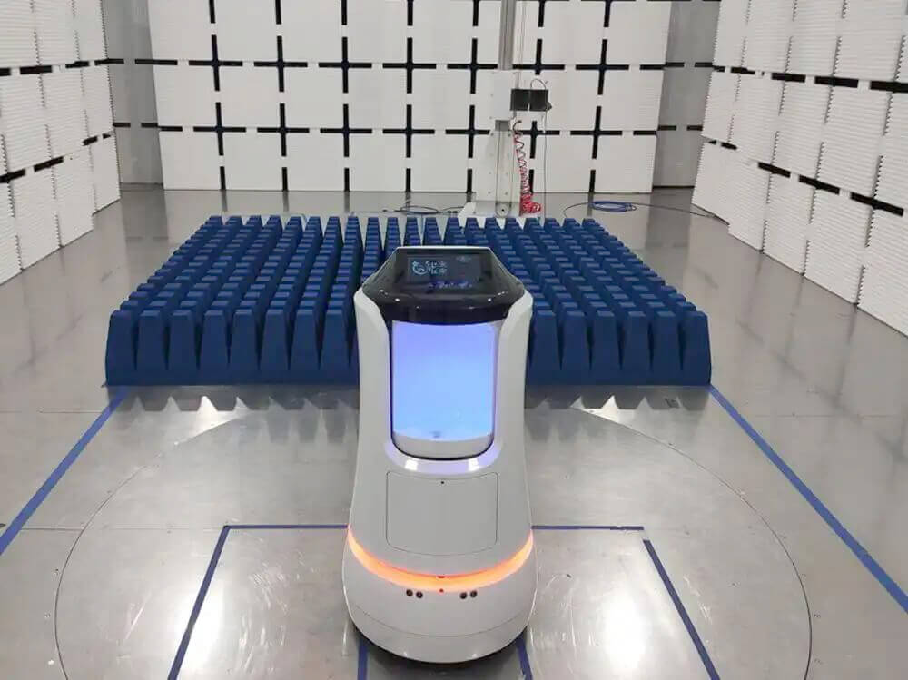
For laboratory planning, an electromagnetic shielded chamber provides a useful starting point for understanding shielding and controlled RF environments.

Step 2: Position the EUT and Cable Under Test
The EUT must operate in a representative condition during measurement.
Depending on the product, this may include:
– Motor operation
– Heating cycles
– Switching power supplies
– Electronic control activity
– Variable operating speeds
– Normal power consumption
The cable under test is arranged along the measurement rail and passed through the absorbing clamp.
For a typical tabletop arrangement under CISPR 14-1, the EUT is placed on a non-metallic support, and the straight cable section is maintained approximately 0.8 m above the floor.
The required cable length is generally around 6 m to provide sufficient travel for locating the maximum disturbance level.
Cable placement should remain consistent throughout testing.
Bending, coiling, or moving the cable during a measurement can change its RF behavior and affect the recorded result.
Step 3: Install the Absorbing Clamp
The absorbing clamp is the main RF measurement device.
It combines current-sensing and absorbing elements to measure RF disturbances associated with the cable while reducing the influence of unwanted signals arriving from the far end of the cable.
During installation:
1. Open the absorbing clamp.
2. Place the cable under test through the clamp aperture.
3. Close and secure the clamp according to its instructions.
4. Position the clamp on the moving carriage.
5. Connect the clamp RF output to the EMI receiver.
6. Check that the clamp can move freely along the required scanning distance.
The clamp must be suitable for the required measurement frequency range and calibrated according to the applicable CISPR requirements.
Clamp orientation and reference position should follow the relevant test procedure.
Step 4: Configure the Automated Test Rail
Manual movement of an absorbing clamp can be time-consuming, especially when many frequencies must be evaluated.
An automated rail provides controlled movement and repeatable clamp positioning.
The GE Conducted Disturbance Power Test System uses the GEDPR-6000 test rail together with the GEC-3 controller.

The standard GEDPR-6000 configuration includes:
– Total rail length: 6.0 m
– Effective scanning length: 5.1 m
– Rail upper-surface height: 0.8 m
– Adjustable scanning speed: 1–50 cm/s
– Positioning accuracy: ±0.5 cm
– Non-metallic PVC and fiberglass structure
– Kevlar-reinforced drive belt
– Polymer optical-fiber communication
The rail is designed to move the absorbing clamp along the cable while minimizing electromagnetic interference from the positioning equipment.
Its non-metallic construction also helps limit unwanted reflections around the measurement path.
The full conducted disturbance power test system range provides additional product information.
Step 5: Connect the Controller and EMI Receiver
The GEC-3 controller manages the automated movement of the test rail.
It communicates with the rail through optical fiber, separating the motion-control communication from the RF measurement environment.
The controller supports interfaces including:
– RJ45 / TCP/IP
– USB
– RS232
– Optical-fiber connections
After connecting the controller, configure:
– Rail reference position
– Starting position
– Scanning distance
– Movement speed
– Position limits
– Software communication
The EMI receiver is connected to the absorbing clamp through a suitable 50-ohm RF measurement cable.
The measurement software should coordinate receiver readings with clamp position so that maximum disturbances can be associated with the correct location along the cable.
Step 6: Perform a Background Noise Check
Before powering the EUT, verify the background RF noise level.
Background measurements help identify unwanted signals originating from:
– Power supplies
– Positioning motors
– Control electronics
– Nearby transmitters
– Laboratory equipment
– External RF sources
The disturbance power test system should not generate interference that masks emissions from the EUT.
If unexpected background peaks appear, check the controller, power connections, shielded drive enclosure, and RF measurement cable routing.
A background check is particularly important when measuring products with low disturbance levels.
Step 7: Perform the Absorbing Clamp Scan
During the measurement, the absorbing clamp is moved along the straight cable section.
The purpose is to find the position where the RF disturbance produces the highest receiver indication at each relevant frequency.
This position changes with frequency because the cable and clamp arrangement behaves as an RF transmission system.
A practical measurement sequence includes:
1. Operate the EUT in the specified test mode.
2. Select the required frequency range.
3. Perform an initial receiver scan.
4. Move the absorbing clamp along the cable.
5. Record maximum levels at relevant frequencies.
6. Repeat measurements using the detector required by the standard.
7. Compare corrected disturbance power with the applicable limit.
The maximum is not necessarily found near the EUT or at the far end of the cable.
This is why clamp movement is an essential part of the measurement procedure rather than an optional mechanical adjustment.
Step 8: Apply Calibration and Correction Factors
The EMI receiver measures an RF voltage, but the required result is disturbance power.
Conducted disturbance power is commonly expressed in dBpW, meaning decibels relative to 1 picowatt.
The receiver reading must be converted using the calibrated absorbing clamp factor.
In simplified form:
Disturbance Power (dBpW) = Receiver Level (dBµV) + Clamp Factor
Any RF cable correction not already included in the calibrated measurement-chain factor must also be accounted for.
The clamp factor changes with frequency, so the correct calibration data should be loaded into the EMC measurement software.
Using an incorrect clamp factor can shift the final measurement result and create a false pass or fail.
Calibration status, cable loss, receiver settings, and test-site characteristics should all be verified before formal measurements.
Common Setup Errors That Affect Results
Several practical issues can cause inconsistent disturbance power measurements.
Incorrect Cable Length
A cable that is too short may prevent the clamp from reaching the position where maximum disturbance power occurs.
Nearby Metallic Objects
Conductive structures can alter RF coupling and measurement-site characteristics.
Unstable EUT Operation
Changing motor speed, load, or switching behavior may change the generated interference.
Incorrect Clamp Orientation
The absorbing clamp must be installed and oriented according to its calibration and test procedure.
RF Cable Movement
Moving the receiver cable with the clamp can introduce mechanical stress and additional measurement variation.
Incorrect Correction Data
Using the wrong clamp factor or receiver configuration can produce inaccurate disturbance power values.
Automated movement improves positioning repeatability, but it does not eliminate the need for correct site preparation and calibration.
Conducted Disturbance Power vs. LISN Testing
Conducted disturbance power testing should not be confused with conventional conducted emission voltage testing.
A LISN-based test generally measures disturbance voltage on power lines, commonly from 150 kHz to 30 MHz.
The absorbing clamp method measures disturbance power associated with connected cables, typically in a higher RF range.
| Parameter | LISN Conducted Emissions | Absorbing Clamp Disturbance Power |
|---|---|---|
| Main instrument | LISN | Absorbing clamp |
| Typical range | 150 kHz–30 MHz | 30–300 MHz for applicable CISPR 14-1 tests |
| Measurement quantity | Disturbance voltage | Disturbance power |
| Result unit | dBµV | dBpW |
| Mechanical movement | No clamp scan | Clamp-position scan |
The two methods provide different information and are not interchangeable.
For a detailed explanation of conventional conducted emissions, see How Conducted Emission Test Works and How LISN Works in EMC Testing.
Practical System Setup Checklist
Before starting a conducted disturbance power test, verify:
– Applicable CISPR test method and frequency range
– EUT operating mode and power requirements
– Correct absorbing clamp and calibration data
– Suitable test-site conditions
– Required cable length and support height
– Adequate clearance from conductive objects
– Correct clamp orientation
– Full rail travel without obstruction
– Controller communication and positioning accuracy
– EMI receiver configuration
– RF cable correction
– Background noise performance
– Maximum-level search procedure
– Applicable disturbance power limits
A properly configured system combines a calibrated absorbing clamp with controlled cable positioning, suitable RF measurement equipment, and automated motion.
The GEDPR-6000 Conducted Disturbance Power Test System provides the positioning and control functions needed to automate the clamp movement, while the absorbing clamp, EMI receiver, and calibration data determine the actual RF measurement performance.