

Selecting an EMC antenna is not simply a matter of finding a model whose published frequency range covers the required test band. Two antennas may cover the same frequencies but perform very differently once they are connected to an EMI receiver, RF power amplifier, cable network, antenna mast, and test chamber.
For reliable radiated emissions and radiated immunity testing, four specifications deserve particular attention:
* Frequency range
* Antenna factor
* Voltage standing wave ratio, or VSWR
* RF power handling
These parameters affect measurement sensitivity, field-strength generation, amplifier loading, calibration stability, and the amount of test equipment required to cover the complete EMC test range.
The right EMC antenna therefore has to be selected as part of the complete measurement system rather than as an isolated component. A typical EMC measurement system may include an EMI receiver or signal generator, RF amplifier, coaxial cables, antenna, field probe, antenna mast, turntable, and semi-anechoic chamber.
Start with the Actual EMC Test Frequency Range
Frequency range is the first filter in EMC antenna selection, but the widest available bandwidth is not automatically the best choice.
The required range depends on:
* The applicable EMC standard
* Whether the test is for radiated emissions or radiated immunity
* The operating frequencies of the equipment under test
* The upper frequency limit required by the product standard
* The available RF amplifier bands
* Chamber size and antenna-to-EUT distance
Radiated emissions measurements frequently begin around 30 MHz, although the upper limit may extend from 1 GHz to several gigahertz depending on the equipment and applicable standard. Radiated immunity testing may begin at 80 MHz or lower and can extend to 6 GHz, 18 GHz, or higher for specialized applications.
This is why an EMC laboratory may use several antenna types rather than one universal antenna.
Biconical Antennas for Lower Frequencies
Biconical antennas are commonly used in the lower VHF portion of radiated emissions and radiated immunity testing. Their broad radiation pattern and relatively simple construction make them practical for low-frequency measurements, where antenna dimensions become larger.
For example, the OBC-022-3KW-4 Biconical Antenna covers 20 MHz to 200 MHz, with a listed VSWR of 2.0:1 and power handling of 3000 W. This combination makes it suitable for lower-frequency applications that require both broadband coverage and substantial RF input power.
A lower-power model may be entirely adequate for emissions measurements, but immunity testing at the same frequencies can require considerably more RF power. The antenna specification should therefore be matched to the test direction, not only to the frequency band.
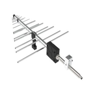
Log-Periodic Antennas for VHF, UHF, and Lower Microwave Bands
Log-periodic antennas provide directional radiation, relatively stable gain, and wide operating bandwidth. They are widely used for both receiving radiated emissions and transmitting RF fields during immunity testing.
The OLP-00810 Log-Periodic Antenna covers 80 MHz to 1 GHz, with a typical VSWR of 1.5:1, typical gain of 7.5 dBi, and listed maximum power handling of 3000 W. This is a useful frequency range for many radiated immunity systems where high field strength must be generated across the VHF and UHF bands.
Another option, the 1313-2-80M1G Log-Periodic Antenna, also covers 80 MHz to 1 GHz. It is rated for a maximum input power of 1000 W and is designed to produce high-intensity RF fields, with average gain specified at 7.5 dBi.
Although both antennas cover a similar band, their VSWR limits, gain characteristics, power ratings, mechanical dimensions, and field-generation performance are not identical. Frequency coverage alone is therefore insufficient for selecting between them.
Hybrid Antennas for Wider Test Coverage
A hybrid biconical/log-periodic design can reduce antenna changes by covering the lower VHF range through several gigahertz.
The OVLP-00360 High-Performance Log-Periodic Antenna covers 30 MHz to 6 GHz, with typical VSWR below 2:1, typical gain of 8.5 dBi, and maximum input power listed at 225 W. Its wide frequency range is useful for automated EMC measurements where reducing antenna changes and test interruptions is important.
However, its 225 W power rating is much lower than the rating of some dedicated immunity antennas. It may provide excellent bandwidth for emissions measurements and moderate-field immunity applications, but a higher-power antenna may still be required when the target field strength, chamber losses, test distance, or low-frequency efficiency demands more amplifier power.
Wide bandwidth improves convenience. It does not remove the need to calculate the required forward power.

Dual-Ridged Horn Antennas for Higher Frequencies
Above approximately 1 GHz, dual-ridged horn antennas are often used because they provide directional gain, wide bandwidth, and suitable radiation characteristics for microwave EMC and RF testing.
The OBH-08180 Broadband Dual-Ridged Horn Antenna covers 0.8 GHz to 18 GHz. Its published specifications include gain from 5 to 14 dBi, a typical VSWR of 1.5:1, and maximum power handling of 1500 W. This range allows one antenna to support testing across several microwave communication, radar, satellite, wireless, and EMC bands.
In practice, the complete test path still has to support the same range. A broadband antenna cannot compensate for an amplifier, directional coupler, cable, or connector that cannot operate efficiently at the required frequency.
Why Antenna Factor Matters in Radiated Emissions Testing
Antenna factor is one of the most important specifications for a radiated emissions antenna.
It describes the relationship between the electric field incident on the antenna and the voltage produced at the antenna output:
Antenna Factor = Electric Field Strength / Received Voltage
In logarithmic units, the antenna factor is normally expressed in dB/m. During radiated emissions testing, the measured receiver voltage is corrected using the antenna factor and the losses or gains in the measurement path:
Field Strength = Receiver Reading + Antenna Factor + Cable Loss − Preamplifier Gain
For example, if the EMI receiver measures 40 dBµV and the antenna factor at that frequency is 15 dB/m, the uncorrected field-strength result is 55 dBµV/m before cable-loss and preamplifier corrections are applied.
A Lower Antenna Factor Improves Measurement Sensitivity
For the same incident electromagnetic field, an antenna with a lower antenna factor produces a higher voltage at the receiver input.
This can improve measurement sensitivity when:
* The emissions are close to the system noise floor
* Long RF cables introduce significant insertion loss
* The test frequency is near the antenna’s lower operating limit
* The applicable emissions limit is particularly low
* A preamplifier cannot be used because of overload or linearity concerns
A low antenna factor is especially valuable when measuring weak radiated emissions. However, the value must be considered across the complete frequency range. A single minimum antenna-factor figure does not show how the antenna performs at every measurement point.
The OVLP-00330 High-Performance Log-Periodic Antenna covers 30 MHz to 3 GHz and is supplied with detailed calibration data across 533 frequency points. Its design combines wide bandwidth, gain, and a relatively low antenna factor for EMC emissions and immunity measurements.
Calibration Data Is More Important Than a Marketing Value
A published statement such as “low antenna factor” is not sufficient for compliance testing.
The laboratory needs traceable antenna-factor data at appropriate frequency intervals. The calibration documentation should clearly identify:
* Calibration frequency points
* Measurement distance
* Antenna polarization
* Free-space or site-specific calibration conditions
* Measurement uncertainty
* Applicable correction factors
* Antenna serial number
Two antennas of the same model may have small differences caused by element dimensions, balun performance, assembly tolerances, connector condition, or previous handling. For this reason, individually calibrated antenna-factor data should be entered into the EMC software rather than relying on a generic catalog curve.
Antenna factor is primarily a receiving-antenna parameter. During radiated immunity testing, antenna gain, VSWR, power handling, field uniformity, and amplifier power requirements generally become more important.
How VSWR Affects RF Power Transfer
VSWR indicates how closely the antenna input impedance is matched to the 50-ohm RF system.
When the antenna impedance does not match the cable and amplifier output impedance, part of the forward RF power is reflected toward the amplifier. This reduces the power delivered to the antenna and can place additional stress on the amplifier output stage.
The effect becomes clearer when VSWR is converted into reflected power:
Antenna VSWR Approximate Reflected Power
1.5:1 4%
2.0:1 11%
3.0:1 25%
An antenna with a 1.5:1 VSWR therefore transfers RF power more efficiently than an antenna operating at 3.0:1, assuming the other system conditions are the same.
VSWR Is Not Constant Across the Frequency Range
The VSWR shown on a product page may be:
* A typical value
* A maximum value
* An average value
* A value that applies only to part of the frequency band
The full VSWR curve is more useful than a single headline specification. Broadband antennas often have localized frequency regions where the impedance match becomes worse. These peaks may determine the actual amplifier power required during field calibration.
The OLP-230 Log-Periodic Antenna covers 200 MHz to 3 GHz and specifies VSWR below 2:1. Its combination of directional gain and relatively low VSWR helps reduce reflected power and makes better use of the available RF amplifier output.
Why VSWR Is Especially Important in Immunity Testing
During radiated emissions testing, the antenna is receiving very small signals. A moderate mismatch may reduce sensitivity, but the absolute RF power involved is minimal.
During radiated immunity testing, the antenna may be driven with hundreds or thousands of watts. Poor matching can lead to:
* Higher reflected power
* Reduced field strength at the EUT
* Amplifier foldback or shutdown
* Greater heating in cables and connectors
* Unstable field calibration
* Higher amplifier capacity requirements
* Longer dwell times while the control system corrects the field level
A high-power amplifier does not guarantee a high test field if a significant part of its output is reflected or lost in the RF path.
The relevant figure is the net power delivered to the antenna after cable loss, connector loss, directional-coupler loss, and mismatch are taken into account.
Power Handling Determines Whether the Antenna Can Safely Generate the Required Field
Power handling is often treated as a simple maximum-input figure, but the real selection process is more complicated.
The required antenna rating depends on:
* Target field strength
* Antenna gain
* Test distance
* Chamber loading
* Cable and connector loss
* VSWR at each frequency
* Amplifier output power
* Continuous-wave or pulsed operation
* Modulation and dwell time
* Test duration and duty cycle
An antenna may survive a short high-power pulse but overheat during continuous-wave operation at the same peak level. Unless the specification clearly states otherwise, pulse power and continuous power should not be treated as interchangeable.
High Power Is Usually Needed at the Least Efficient Frequencies
The highest RF power demand often appears near the lower end of an antenna’s operating range, where its physical dimensions are small relative to the wavelength and its gain may be lower.
For this reason, a wideband immunity antenna should be evaluated using its complete gain and VSWR curves. The test-system designer needs to identify the frequency where the combination of low gain, high VSWR, cable loss, and chamber loss creates the worst-case power requirement.
A product listed as covering 30 MHz to 6 GHz may operate throughout that range, but it may not generate the same field strength at every frequency with the same amplifier power.
Add Practical Power Margin
Operating continuously at the antenna’s absolute power limit is poor system design. A practical EMC immunity system needs margin for:
* Field-uniformity correction
* Frequency-dependent chamber losses
* Cable aging
* Connector replacement
* Amplifier gain variation
* Calibration uncertainty
* Future increases in test level
* Changes in antenna distance or EUT size
Antenna power handling should also be checked at the weakest frequency, not only at the center of the band.
High-power models such as the 20–200 MHz OBC-022-3KW-4 biconical antenna and the 80 MHz–1 GHz OLP-00810 log-periodic antenna can support demanding immunity applications, while a lower-power wideband antenna may be more appropriate for emissions measurements, monitoring, field surveys, or lower-field-strength immunity testing.
Emissions and Immunity Antennas Should Not Be Selected the Same Way
An antenna that performs well in radiated emissions testing is not automatically the best choice for radiated immunity testing.
For Radiated Emissions Testing, Prioritize:
* Calibrated antenna-factor data
* Low antenna factor
* Receiver sensitivity
* Stable radiation pattern
* Suitable polarization characteristics
* Low cable loss
* Traceable calibration uncertainty
* Compatibility with the antenna mast and measurement distance
The antenna must convert weak electromagnetic fields into a measurable receiver voltage without adding excessive uncertainty to the result.
For Radiated Immunity Testing, Prioritize:
* Antenna gain
* VSWR across the complete band
* Continuous RF power handling
* Field-strength capability
* Radiation-pattern stability
* Field-uniformity performance
* Connector and cable power ratings
* Compatibility with the RF amplifier
The objective is no longer to detect a weak signal. It is to generate a controlled and repeatable electromagnetic field over the calibrated test area.
Some broadband EMC antennas can perform both functions, but the selection criteria remain different for each test direction.
One Wideband Antenna or Several Specialized Antennas?
Using one antenna across a very wide frequency range can reduce:
* Antenna changeovers
* Test interruptions
* Mast repositioning
* Cable reconnection
* Automation complexity
* Total measurement time
This can be useful in commercial laboratories and production environments where test throughput matters.
However, dividing the test range between several antennas may provide:
* Lower antenna factor during emissions testing
* Better impedance matching
* Higher gain
* Higher power handling
* More stable radiation patterns
* Lower amplifier power requirements
* Better field uniformity
A laboratory covering 30 MHz to 18 GHz may therefore use a combination such as:
1. A biconical antenna for the lower-frequency range
2. A log-periodic or hybrid antenna for VHF, UHF, and lower microwave frequencies
3. A dual-ridged horn antenna for the higher microwave range
The transition frequencies should be selected from actual calibration data rather than only from the catalog limits. Where two antennas overlap, the laboratory can compare antenna factor, gain, VSWR, system noise floor, and available amplifier power to determine the more efficient operating range for each model.
The complete range of EMC and RF antennas includes biconical antennas, log-periodic antennas, hybrid antennas, loop antennas, and broadband dual-ridged horn antennas for different emissions, immunity, RF measurement, and field-generation requirements.
Practical EMC Antenna Selection Checklist
Before selecting an EMC test antenna, confirm the following information:
Test Requirements
* Applicable EMC standard
* Radiated emissions, radiated immunity, or both
* Minimum and maximum test frequency
* Required field strength
* Measurement distance
* Required antenna polarization
* CW, pulse, or modulated RF signal
Receiving Performance
* Antenna factor across the complete range
* Calibration frequency interval
* Calibration distance and method
* Measurement uncertainty
* Cable-loss correction
* System noise floor
Transmitting Performance
* Antenna gain versus frequency
* Typical and maximum VSWR
* Maximum continuous input power
* Connector power rating
* Cable power rating
* Required amplifier output
* Expected reflected power
* Field-uniformity performance
Mechanical and Laboratory Requirements
* Antenna dimensions and weight
* Mounting interface
* Horizontal and vertical polarization adjustment
* Compatibility with the antenna mast
* Chamber clearance
* Minimum distance from absorbers and conductive surfaces
* Cable routing during antenna-height scans
A technically correct EMC antenna selection balances all four main parameters. Frequency range determines whether the antenna can operate in the required band. Antenna factor determines emissions measurement sensitivity. VSWR affects RF power transfer and amplifier loading. Power handling determines whether the antenna can safely generate the required immunity field.










