RF power amplifiers used in EMC immunity testing must deliver stable output power throughout extended test sequences. An amplifier that produces the required field strength during a short calibration may behave differently after operating continuously for several hours.
The main factors are continuous-wave (CW) power capability, RF duty cycle, amplifier efficiency, cooling capacity, and operating temperature.
Insufficient cooling can cause gain drift, reduced output power, thermal protection, or unexpected shutdown. These problems can interrupt automated radiated immunity testing and reduce confidence in the applied test conditions.
For EMC laboratories, amplifier performance should therefore be evaluated under realistic operating conditions, not only from maximum output-power specifications.
What Does Duty Cycle Mean for an RF Power Amplifier?
RF duty cycle describes the proportion of time an RF signal is actively transmitted within a defined period.
For a pulsed RF signal:
Duty Cycle (%) = Pulse Width / Pulse Period × 100
For example, an RF amplifier producing 1 ms pulses every 10 ms operates at a 10% RF duty cycle.
A simplified comparison is:
| Operating Mode | RF Duty Cycle | Main Consideration |
|---|---|---|
| Continuous wave (CW) | 100% | Sustained output and cooling |
| Pulsed RF, 50% duty | 50% | Peak power and average heating |
| Pulsed RF, 10% duty | 10% | High peak power with lower average RF output |
| Pulsed RF, 1% duty | 1% | Short pulses and peak-power capability |
A lower RF duty cycle generally reduces average RF output power, but actual heat dissipation also depends on amplifier design and power consumption during the off period.
An amplifier rated for high pulsed output cannot automatically deliver the same power continuously.
CW Power vs. Pulsed Power
One of the most important specifications for an EMC immunity amplifier is its continuous output-power rating.
A CW-rated RF amplifier is designed to support sustained RF output under its specified operating conditions.
A pulsed RF amplifier may deliver substantially higher peak power for short intervals, but its allowable pulse width, repetition rate, and duty cycle are limited.
For example, an amplifier capable of 1,000 W peak output at a 10% duty cycle should not be assumed to provide 1,000 W continuously.
For ideal rectangular RF pulses, 1,000 W peak power at 10% duty corresponds to approximately 100 W average RF output.
However, amplifier heat dissipation cannot be calculated from RF output duty cycle alone. Power-supply losses, bias conditions, and cooling design also matter.
When comparing amplifiers for IEC 61000-4-3 radiated immunity testing, the guaranteed CW output and operating conditions are generally more useful than a peak-power figure alone.
Why Continuous EMC Testing Creates Thermal Stress
RF amplifiers are not perfectly efficient.
Only part of the electrical input power becomes useful RF output. The remaining energy is largely converted into heat.
A simplified relationship is:
Heat Dissipation ≈ Electrical Input Power − RF Output Power
For example, consider an amplifier consuming 1,000 W from its electrical supply while delivering 300 W of RF output.
Approximately 700 W must be dissipated as heat within the amplifier system, assuming the stated input includes its associated internal consumption.
The actual value depends on amplifier efficiency, operating frequency, output level, and design.
During extended EMC immunity testing, this heat must be removed continuously.
If the cooling system cannot maintain acceptable component temperatures, the amplifier may reduce output or activate protection circuits.
Air Cooling vs. Liquid Cooling
Two common cooling approaches are used in high-power RF amplifier systems.
Forced-Air Cooling
Forced-air cooling uses fans to move air through heatsinks and internal RF modules.
Advantages include:
– Relatively simple installation
– No external coolant circuit
– Straightforward maintenance
– Suitability for many laboratory amplifiers
However, airflow must not be obstructed by rack panels, cables, or nearby equipment.
Liquid Cooling
Liquid cooling transfers heat through a coolant circuit connected to the amplifier’s thermal management system.
It is commonly considered for higher-power installations where air cooling becomes less practical.
Liquid-cooled systems require suitable coolant flow, temperature control, leak monitoring, and maintenance.
The better option depends on amplifier heat output, laboratory infrastructure, and continuous operating requirements rather than RF wattage alone.
Rack Installation and Ambient Temperature
Even a properly designed cooling system can perform poorly when an amplifier is installed incorrectly.
High-power RF amplifiers are often installed in equipment racks together with signal generators, RF switches, controllers, and power distribution equipment.
Common installation problems include:
– Blocked air intake or exhaust
– Recirculation of hot exhaust air
– Insufficient rack ventilation
– Excessive ambient temperature
– Dust accumulation
– Incorrect equipment spacing
Some amplifiers use front-to-rear airflow, while others use different ventilation arrangements.
Installation clearance should follow the actual amplifier manufacturer’s requirements.
Laboratories should also consider the total heat released by the RF equipment rack when sizing room air conditioning.
An amplifier operating within its rated ambient temperature range is less likely to experience thermal derating during extended tests.
How Temperature Affects RF Output Stability
As internal temperature increases, RF amplifier performance can change.
Depending on the amplifier design, temperature effects may include:
– Gain variation
– Reduced available output power
– Changes in compression behavior
– Increased cooling-fan speed
– Automatic power reduction
– Thermal shutdown
These effects become important when an automated EMC immunity sweep operates near the amplifier’s maximum usable output.
For example, a system may achieve 10 V/m during initial field calibration but later experience reduced available RF power at frequencies where the amplifier has limited margin.
This does not necessarily mean the antenna or chamber has changed.
The amplifier may be approaching its thermal operating limit.
For related fault symptoms, see Common Signs of Insufficient RF Amplifier Power in EMC Testing.
Does 80% AM Mean an 80% Duty Cycle?
No. 80% amplitude modulation and 80% RF duty cycle describe different characteristics.
IEC 61000-4-3 commonly uses 80% amplitude modulation at 1 kHz.
In this case, the RF carrier amplitude varies continuously according to the modulation waveform. The RF output is not simply switched on for 80% of the time and off for 20%.
Amplitude modulation also creates envelope peaks above the unmodulated carrier level.
For ideal sinusoidal 80% AM:
– Peak envelope power is 3.24 times carrier power.
– Average RF power is 1.32 times carrier power.
The amplifier must support both the required peak envelope and sustained operating conditions without unacceptable compression or overheating.
The detailed relationship is covered in RF Amplifier Linearity and Modulation in EMC Immunity Testing.
Why Long Immunity Sweeps Can Reveal Cooling Problems
Automated radiated immunity testing may involve hundreds or thousands of frequency steps.
At each frequency, the system applies the specified RF field while monitoring EUT performance.
The total test duration depends on frequency step size, dwell time, modulation, EUT monitoring requirements, and repeated test configurations.
Even when there are short interruptions between frequencies, the amplifier may remain powered and thermally loaded throughout the sequence.
Cooling problems may appear only after extended operation.
A useful system verification compares amplifier behavior:
– Shortly after startup
– After thermal stabilization
– During sustained high-power operation
– At frequencies requiring maximum calibrated forward power
This helps reveal output drift that may not appear during a short functional test.
Reflected Power Can Add Thermal Stress
Poor antenna impedance matching can also affect amplifier operation.
When the transmitting antenna has high VSWR, part of the forward RF power is reflected toward the amplifier.
Depending on the output-stage and protection design, reflected power may increase thermal loading or activate automatic output reduction.
This can produce symptoms similar to insufficient cooling:
– Unexpected forward-power reduction
– Amplifier fault warnings
– Output instability
– Intermittent shutdown
Before diagnosing a thermal failure, inspect antenna VSWR, RF cables, connectors, and directional coupler readings.
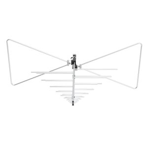
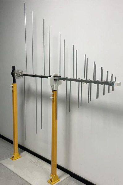
A high-power antenna such as the 1313-2-80M1G Log Periodic Antenna must still be evaluated for impedance matching across its operating range.
Antenna power handling does not guarantee that the connected amplifier can operate continuously under every mismatch condition.
How to Identify Amplifier Overheating
Several symptoms can indicate insufficient cooling or excessive thermal load.
| Observed Symptom | Possible Cause | Recommended Check |
|---|---|---|
| Output drops after prolonged operation | Thermal derating | Monitor temperature and output power |
| Cooling fans run at maximum speed | High internal temperature | Check airflow and ambient temperature |
| Amplifier shuts down during a sweep | Over-temperature protection | Review fault logs and ventilation |
| Output changes after warm-up | Temperature-dependent gain | Compare cold and stabilized performance |
| Power drops at specific frequencies | Compression or mismatch | Check forward/reflected power and frequency response |
These symptoms are diagnostic clues rather than proof of overheating.
A controlled check of temperatures, RF output, reflected power, and amplifier status is needed to identify the actual cause.
Maintaining Stable Output During Continuous Testing
A practical thermal management procedure should include:
– Confirm the amplifier’s rated CW output power.
– Check permitted ambient operating temperature.
– Maintain the specified intake and exhaust clearance.
– Keep cooling fans and air filters clean.
– Monitor amplifier temperature and protection status.
– Review forward and reflected power during extended tests.
– Allow required warm-up before critical measurements.
– Check for thermal derating at high-output frequencies.
– Follow manufacturer maintenance instructions.
For an EMC laboratory, it is also useful to record amplifier fault events and correlate them with test frequency, output power, and operating time.
Repeated shutdowns or unexplained power reductions should be investigated before continuing formal immunity testing.
Selecting an Amplifier for Continuous EMC Operation
When specifying a power amplifier for continuous radiated immunity testing, the following requirements should be confirmed:
– Guaranteed CW power across the required frequency band
– Permitted RF duty cycle for pulsed operation
– Peak and average power ratings
– Linear output capability under modulation
– Thermal derating characteristics
– Cooling method and heat dissipation
– Ambient temperature limits
– Reflected-power protection
– Temperature and fault monitoring
– Rack and ventilation requirements
– Required field-strength margin
– Continuous operating capability during extended sweeps
For broader system-selection criteria, see How to Select an RF Power Amplifier for EMC Testing.
In continuous EMC immunity testing, stable RF output over the entire test duration is more important than maximum power achieved during a short measurement. Cooling capacity, duty cycle, amplifier efficiency, and thermal protection must therefore be evaluated alongside frequency coverage, linearity, and output power.