

Radiated immunity testing is designed to verify whether electronic equipment can continue operating correctly when exposed to radio-frequency electromagnetic fields.
The RF signal generator creates the required test frequency and modulation, but its output power is far too low to generate the electric field levels required inside an EMC chamber. An RF power amplifier is therefore placed between the signal generator and the transmitting antenna to raise the signal to a usable power level.
A typical IEC 61000-4-3 radiated immunity test setup includes:
* RF signal generator
* RF power amplifier
* Directional coupler
* Power meter
* EMC transmitting antenna
* Electric field probe
* Anechoic or semi-anechoic chamber
* EUT monitoring equipment
* EMC control software
The amplifier is one of the main components that determines whether the system can achieve the required field strength across the complete test frequency range.
Why the Signal Generator Alone Is Not Enough
An RF signal generator is designed to produce an accurate frequency, signal level, and modulation waveform. Its output is normally measured in milliwatts or low dBm levels.
Radiated immunity testing requires much more RF power.
The transmitting antenna must convert electrical RF power into an electromagnetic field strong enough to expose the equipment under test at the required distance.
Common IEC 61000-4-3 applications may use field strengths such as 3 V/m or 10 V/m, while industrial, automotive, aerospace, and other specialized immunity tests can require substantially higher levels. The actual requirement comes from the applicable product or industry standard.
Generating these fields may require tens, hundreds, or even more watts of RF power depending on:
* Required field strength
* Test distance
* Antenna gain
* Antenna VSWR
* RF cable loss
* Chamber absorber loss
* Field uniformity
* Frequency
* Modulation
* EUT size
The signal generator controls the RF signal. The RF power amplifier provides the energy needed to turn that signal into the required electromagnetic field.
Field Strength Depends on More Than Amplifier Power
Using a higher-power amplifier does not automatically produce a proportionally stronger field at the EUT.
The RF power has to travel through the complete transmission path:
Signal Generator → RF Power Amplifier → Cable → Directional Coupler → Antenna → Test Field
Loss can occur at every stage.
For a simplified far-field estimate, electric field strength is related to transmitted power, antenna gain, and distance approximately by:
E ≈ √(30 × P × G) / r
where:
* E is electric field strength in V/m
* P is RF power delivered to the antenna in watts
* G is antenna gain as a linear ratio
* r is distance in meters
This relationship is useful for initial system sizing, but an EMC chamber is not an ideal free-space environment. Final amplifier requirements should be based on actual field calibration inside the chamber.
Absorber performance, reflections, antenna position, test volume, and cable routing can all change the power required at individual frequencies.
Antenna Gain Directly Affects Amplifier Requirements
Antenna gain determines how efficiently RF energy is directed toward the test area.
For the same amplifier output, a higher-gain antenna can generally generate a stronger field in its main beam than a lower-gain antenna.
This is why antenna selection and amplifier sizing should be performed together.
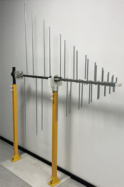
For example, the 1313-2-80M1G log-periodic antenna covers 80 MHz to 1 GHz, with an average gain of 7.5 dBi and maximum RF input power of 1000 W. It is designed for high-intensity RF field generation as well as emissions measurements.
At higher frequencies, a directional horn can reduce the amplifier power needed to reach the same field level. The [OBH-08180 broadband dual-ridged horn antenna](/product/broadband-dual-ridged-horn-antenna-obh-08180/) covers 0.8 GHz to 18 GHz with gain increasing from approximately 5 to 14 dBi.
Higher gain, however, usually comes with a narrower beam. An antenna may generate a strong field at the center of the test area while providing insufficient field strength near the edges.
For radiated immunity testing, amplifier power, antenna gain, beamwidth, and field uniformity must be considered together.
Why One RF Amplifier Usually Cannot Cover the Entire Test Range
Radiated immunity testing can span a very wide frequency range.
An amplifier optimized for 80 MHz to 1 GHz will not normally provide the same output power, efficiency, and gain at several gigahertz.
For this reason, broadband EMC immunity systems often divide the frequency range between several RF power amplifiers.
A typical arrangement might use separate amplifier bands for:
* Lower VHF and UHF frequencies
* 1 GHz to several gigahertz
* Higher microwave frequencies
The exact division depends on the required standard and available test equipment.
Using several narrower-band amplifiers can provide:
* Higher available output power
* Better efficiency
* More stable gain
* Lower thermal stress
* Better harmonic performance
* More economical system design
An RF switch matrix or automated control system can select the required amplifier and antenna as the test frequency changes.
Broadband antennas may reduce antenna changes, but they do not necessarily eliminate amplifier switching. This is discussed further in How Broadband Antennas Improve EMC Test Efficiency.
The Lowest-Gain Frequency Often Determines Amplifier Size
When engineers size an immunity amplifier, looking only at the antenna’s average gain can be misleading.
A broadband antenna does not have constant gain across its entire operating range.
At some frequencies the antenna may provide high gain and require relatively little amplifier power. At other frequencies, particularly near the lower end of the antenna range, its gain may fall and substantially more power may be required.
The worst-case point may also coincide with:
* Higher antenna VSWR
* Greater cable loss
* Lower amplifier output
* Increased chamber loss
* Poorer field uniformity
The amplifier should therefore be selected from the worst-case system power requirement rather than from the average performance of the antenna.
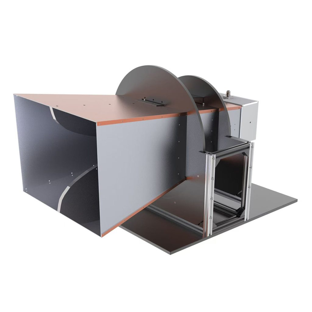
The OBH-460-HG ultra-wide-band dual-ridged horn antenna illustrates this frequency-dependent behavior. It covers 0.4 GHz to 6 GHz, with gain specified from 6 to 19 dBi and input power capability varying across the range.
VSWR and Reflected Power
Not all power leaving the amplifier reaches the antenna efficiently.
When the antenna impedance does not match the 50-ohm RF system, some energy is reflected back toward the amplifier.
Higher VSWR means more reflected power.
This can cause:
* Reduced power delivered to the antenna
* Lower test field strength
* Amplifier foldback
* Output-power instability
* Increased heating
* Protective shutdown
* Greater calibration time
The amplifier must therefore tolerate the expected mismatch in the actual test system.
The antenna VSWR curve should be reviewed across the complete frequency range rather than relying only on a typical catalog value.
A detailed discussion of this relationship is available in How Frequency Range, Antenna Factor, VSWR, and Power Handling Affect EMC Antenna Selection.
Cable Loss Can Consume Significant RF Power
The RF cable between the amplifier and antenna also reduces available power.
Cable loss increases with frequency and cable length. At microwave frequencies, several decibels of cable loss can represent a substantial reduction in the power reaching the antenna.
For example, a 3 dB transmission loss means that only about half of the RF power entering that section reaches the other end.
This makes cable selection particularly important in high-frequency immunity systems.
The RF path should use:
* Low-loss coaxial cable
* Suitable high-frequency connectors
* Minimum practical cable length
* Correct connector torque
* High-power-rated adapters
* Proper cable bend radius
Directional couplers, RF switches, adapters, and connectors also introduce insertion loss.
Amplifier sizing should therefore be based on power delivered to the antenna, not simply the rated amplifier output at its connector.
Why Amplifier Headroom Is Necessary
An amplifier should not be selected so that it operates continuously at its absolute maximum output just to reach the required test field.
Practical RF immunity systems need additional power margin.
Headroom is needed for:
* Frequency-dependent antenna gain
* Cable aging
* VSWR changes
* Chamber variation
* Field-uniformity correction
* Modulation peaks
* Amplifier gain drift
* Higher future test levels
If an amplifier is constantly operating near compression, the output waveform may become distorted and the field calibration may become unstable.
Selecting some additional power capacity makes the system more reliable and provides flexibility when test requirements change.
Amplifier Linearity and Modulation
Radiated immunity testing does not always use an unmodulated continuous-wave signal.
IEC 61000-4-3 testing commonly uses amplitude modulation, and other EMC standards may specify different modulation formats.
The amplifier must reproduce the required RF waveform without excessive compression or distortion.
If the amplifier is driven too close to saturation:
* Modulation depth may change
* Harmonics may increase
* Output power may become nonlinear
* Test field strength may fluctuate
* Calibration data may no longer represent the applied signal accurately
Amplifier linearity is therefore important even when the system appears to have enough nominal output power.
The required headroom should be considered with the modulation method during system design.
Field Uniformity Calibration Determines the Real Power Requirement
Before the EUT is exposed, the radiated immunity field is calibrated over the defined test area.
A field probe measures the electric field at multiple positions while the software adjusts RF power.
The purpose is to determine the amplifier output needed to achieve the required field across the test area at each frequency.
The resulting calibration table may show significant variations in required forward power.
A frequency that requires 20 W at one point in the band may require much more power at another because of antenna gain, VSWR, chamber behavior, or cable loss.
This is why amplifier sizing based only on theoretical free-space calculations can be risky.
The actual chamber calibration provides the best indication of whether the available RF power is sufficient.
The complete process is described in How Radiated Immunity Test Is Performed.
High Field Strength Requires More Than a Larger Amplifier
When a test system cannot reach the required V/m level, increasing amplifier power is only one possible solution.
The problem may also be caused by:
* Low antenna gain
* Poor antenna positioning
* Excessive RF cable loss
* High antenna VSWR
* Incorrect antenna polarization
* Poor chamber field distribution
* An oversized test distance
* RF connector damage
Before specifying a much larger amplifier, the complete RF path should be checked.
In some cases, changing to a higher-gain antenna can reduce the amplifier requirement significantly.
In other cases, the antenna beam may become too narrow and reduce field uniformity, so the higher-power amplifier remains the better solution.
Antenna Power Handling Must Match the Amplifier
A powerful RF amplifier requires an antenna that can safely accept its output.
The complete transmission chain must also support the maximum RF power.
Check the ratings of:
* Antenna
* Coaxial cable
* RF switch
* Directional coupler
* Connectors
* Adapters
* Attenuators
* Terminations
For example, an amplifier capable of several hundred watts should not be connected through a cable or RF switch rated for only a fraction of that power.
High VSWR makes this even more important because reflected voltage and current can increase stress on individual components.
The EMC antenna range includes models intended for both receiving measurements and high-power transmitting applications. Antenna power handling should always be checked against the maximum possible amplifier output rather than only the normal calibrated operating level.
Cooling and Continuous Operation
Radiated immunity tests can require the amplifier to operate continuously while the signal sweeps across hundreds or thousands of frequency points.
High-power RF amplifiers generate considerable heat, particularly when operated close to rated output.
The system should provide:
* Adequate ventilation
* Clear airflow paths
* Suitable ambient temperature
* Thermal monitoring
* Protection against over-temperature conditions
* Sufficient rack space
Thermal performance matters because amplifier gain and maximum available power can change as internal temperature rises.
A system that reaches the required field during a short calibration may behave differently during a long-duration immunity test if cooling is inadequate.
What to Check When Selecting an RF Power Amplifier
Before specifying an amplifier for radiated immunity testing, review:
* Required test frequency range
* Maximum required field strength
* Antenna gain versus frequency
* Antenna VSWR
* Test distance
* Cable and RF path loss
* Required modulation
* Continuous output power
* Gain flatness
* Compression characteristics
* Harmonic performance
* Reflected-power tolerance
* Cooling requirements
* Remote-control interface
* Required power margin
* Compatibility with RF switches and directional couplers
* Antenna and cable power ratings
The RF power amplifier should be sized as part of the complete EMC measurement system, together with the antenna, chamber, field probe, RF cables, positioning equipment, and test software.










