RF power amplifiers are essential for generating the electromagnetic fields used in EMC immunity testing. However, producing enough RF output power is only part of the requirement. The amplifier must also reproduce the specified test signal without excessive distortion.
In radiated immunity testing, particularly under IEC 61000-4-3, amplifier linearity and modulation performance directly affect the electromagnetic disturbance applied to the equipment under test (EUT).
An amplifier may generate the required field strength with an unmodulated signal but struggle when amplitude modulation is enabled. This occurs because the modulation envelope requires additional peak power that may exceed the amplifier’s usable linear range.
Understanding this relationship helps EMC laboratories select suitable amplifiers, prevent waveform distortion, and maintain repeatable immunity test conditions.
What RF Amplifier Linearity Means
An RF power amplifier is considered linear when its output signal remains proportional to its input signal.
For example, increasing input power by 3 dB should produce approximately 3 dB more output power while the amplifier remains in its linear operating range.
As the output approaches its maximum capability, the relationship becomes nonlinear. Increasing input drive produces progressively less additional output.
This behavior is known as gain compression.
For EMC immunity testing, excessive compression can cause:
– Reduced modulation depth
– Distorted RF signal envelopes
– Increased harmonic generation
– Incorrect applied test conditions
– Unstable output during frequency sweeps
An amplifier can therefore produce substantial RF power while still being unsuitable for a particular modulated immunity test.
Why IEC 61000-4-3 Uses Amplitude Modulation
IEC 61000-4-3 defines a standardized method for evaluating electronic equipment exposed to radiated RF electromagnetic fields.
A commonly used test condition is:
80% amplitude modulation (AM) at 1 kHz.
In this arrangement, a sinusoidal 1 kHz signal changes the amplitude of the RF carrier.
The modulation simulates amplitude variations that can occur in practical electromagnetic disturbances and helps identify equipment sensitivity to RF envelope detection.
An EUT may respond differently to a modulated RF signal than to an unmodulated continuous-wave signal at the same carrier frequency.
Typical responses include:
– Audio interference
– Sensor reading errors
– Communication instability
– Control circuit malfunction
– Unexpected processor resets
The complete test arrangement is described in IEC 61000-4-3 Radiated Immunity Test Overview.
How 80% AM Changes the Required Amplifier Power
Amplitude modulation creates peaks that are higher than the unmodulated carrier amplitude.
For an ideal sinusoidal AM signal, the maximum envelope amplitude is:
Peak Amplitude = Carrier Amplitude × (1 + m)
where m is the modulation index.
At 80% modulation:
1 + 0.8 = 1.8
The maximum envelope amplitude is therefore 1.8 times the unmodulated carrier amplitude.
Because RF power is proportional to voltage squared, the peak envelope power becomes:
Peak Envelope Power = Carrier Power × 1.8²
Peak Envelope Power = Carrier Power × 3.24
This corresponds to approximately 5.1 dB above the carrier power.
For example, if the required unmodulated carrier power is 100 W, the amplifier must accommodate an ideal peak envelope power of approximately 324 W to reproduce the modulation peaks without compression.
The average power of the ideal 80% AM waveform is lower—approximately 132 W for a 100 W carrier—but average power alone does not establish whether the amplifier can reproduce its peaks accurately.
This distinction is important when comparing RF amplifier specifications.
P1dB, Linear Output Power, and Saturated Power
RF amplifier datasheets may specify several output-power ratings.
P1dB (1 dB Compression Point)
This is the output level where actual amplifier gain has dropped by 1 dB compared with its small-signal linear gain.
It is a useful indicator of the amplifier’s usable output capability, although measurable distortion can already be present at P1dB.
Saturated Output Power (Psat)
This is the power the amplifier approaches when additional input drive produces little further increase in output.
Saturated power is usually higher than P1dB output, but it should not automatically be treated as usable linear power.
Linear Output Power
This describes an operating level meeting a specified linearity or distortion requirement.
For EMC immunity applications using amplitude modulation, the available linear power is generally more relevant than the maximum saturated output.
An amplifier advertised as having 200 W saturated output does not necessarily provide 200 W of sufficiently linear output for 80% AM testing.
For broader equipment-selection criteria, see How to Select an RF Power Amplifier for EMC Testing.
How Amplifier Compression Distorts Modulation
When an amplifier is operated close to saturation, the positive peaks of an AM envelope may become compressed.
Instead of following the intended sinusoidal envelope, the output waveform becomes flattened near its highest amplitude.
This can alter the actual modulation depth and introduce additional distortion.
The effect is important because the EUT should be exposed to the disturbance specified by the applicable EMC test procedure.
If the RF waveform is distorted, the actual electromagnetic exposure may differ from the intended test condition.
A system may therefore appear to generate sufficient RF power while failing to reproduce the required signal accurately.
Increasing signal-generator drive does not correct this situation. It may simply push the amplifier further into compression.
The appropriate solution is to restore linear operating margin or use an amplifier with higher usable output power.
Harmonic Distortion Can Affect Immunity Results
Nonlinear amplification can also generate harmonics at multiples of the intended carrier frequency.
For example, a test performed at 500 MHz may produce unwanted harmonic energy at 1 GHz, 1.5 GHz, and higher frequencies.
If these harmonics reach the transmitting antenna, they may produce additional electromagnetic fields inside the chamber.
This creates a measurement problem.
An EUT malfunction might be caused by a harmonic rather than by the intended carrier frequency.
The risk becomes greater when the transmitting antenna operates efficiently at both the fundamental and harmonic frequencies.
The RF immunity system should therefore be evaluated for harmonic performance, particularly when the amplifier operates at high output power.
Suitable filtering may be necessary in some test configurations.
Field Calibration and Modulated Test Signals
Before radiated immunity testing begins, the electromagnetic field is characterized using a calibrated field probe.
IEC 61000-4-3 field calibration uses an unmodulated RF reference under the specified procedure to establish the required field and associated forward-power values.
The required modulation is then applied during the EUT immunity test.
The amplifier must have sufficient linear capability to reproduce the modulated waveform at the established test setting.
This creates an important distinction:
Reaching the required field during unmodulated calibration does not, by itself, demonstrate adequate amplifier linearity under modulation.
The complete immunity chain must support both the calibrated field level and the modulation requirements.
Field strength also varies with antenna gain, frequency, RF path loss, and test distance.
The relationship between these parameters is explained in How Amplifier Power, Antenna Gain, and Test Distance Determine Field Strength.
Antenna Performance Also Influences Linearity Requirements
Antenna selection affects how much amplifier power is needed to generate the specified field.
At frequencies where antenna gain is low, more RF power may be necessary. This can bring the amplifier closer to compression.
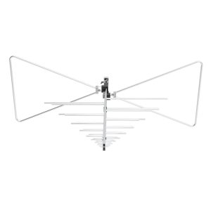
For example, the 1313-2-80M1G Log Periodic Antenna covers 80 MHz to 1 GHz and provides broadband performance for RF field generation.
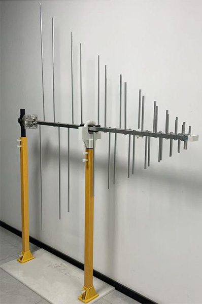
When used with an immunity amplifier, the available linear power should be evaluated against the antenna’s frequency-dependent gain, VSWR, and the required test distance.
A system may have comfortable power margin at 500 MHz but limited linearity margin near another frequency where antenna efficiency is lower.
The worst-case operating frequency is therefore particularly important.
Common Signs of Insufficient Linearity
Several symptoms may indicate that an RF amplifier is operating outside its suitable linear range:
– Output power increases less than expected when input drive rises.
– Measured modulation depth differs from the generator setting.
– The AM envelope becomes flattened or asymmetric.
– Harmonic levels increase sharply at high output.
– Forward power becomes unstable.
– The amplifier enters compression or protection.
– Results differ significantly between expected and measured RF waveform behavior.
These symptoms should be distinguished from problems caused by cable loss, antenna mismatch, or insufficient chamber field uniformity.
See Common Signs of Insufficient RF Amplifier Power in EMC Testing for additional troubleshooting guidance.
Different Immunity Standards May Use Different Modulation Methods
Not every EMC immunity standard uses the same RF modulation.
IEC 61000-4-3 commonly uses 80% AM, while automotive standards such as ISO 11452-2 may specify different signal-leveling or modulation procedures.
Some specialized military or aerospace applications also use pulsed RF signals.
These methods place different demands on amplifier performance.
For example, an application using peak-power conservation cannot automatically use the same carrier-power calculation as a conventional 80% AM test.
Amplifier selection should therefore account for the exact waveform, peak output, average output, compression characteristics, and calibration procedure required by the applicable standard.
Practical Amplifier Linearity Verification
Before using an RF amplifier for EMC immunity testing, the laboratory should verify:
– Output power: Confirm the available CW and linear output across the frequency range.
– Compression: Review P1dB and saturated-power specifications.
– Modulation depth: Check that the amplified AM signal follows the required envelope.
– Peak power: Confirm sufficient headroom for modulation peaks.
– Harmonics: Evaluate unwanted frequency components at high output.
– Load mismatch: Check reflected power and amplifier protection behavior.
– Temperature: Verify stable performance during extended operation.
– Calibration: Confirm that the RF power settings and field calibration remain valid for the required test configuration.
A directional coupler and appropriate RF power measurement equipment can be used to monitor output behavior. Suitable RF waveform measurement equipment may also be required to verify modulation depth and envelope distortion.
For radiated immunity systems, usable linear power is more important than maximum advertised wattage. The amplifier must generate the required electromagnetic field while preserving the signal characteristics specified by the test method.