Insufficient RF amplifier power is a common reason why a radiated immunity test system cannot achieve the required electric field strength. The problem is not always obvious. An amplifier may appear to be operating normally, with no alarm or shutdown, while the field probe shows that the required V/m level cannot be maintained at certain frequencies.
In practice, insufficient RF power often appears as a combination of symptoms: the amplifier reaches its output limit, forward power rises sharply, field strength stops increasing, or only part of the calibrated test area meets the required level.
These signs are especially important during IEC 61000-4-3 radiated immunity testing, where the RF amplifier, antenna, cable path, chamber, and field probe must work together to generate a controlled electromagnetic field.
The Required Field Strength Cannot Be Reached
The clearest sign of insufficient amplifier power is simple: the system cannot reach the required field strength.
For example, the test may require 10 V/m, but the field probe stops at:
* 7 V/m
* 8.5 V/m
* 9 V/m
even though the RF amplifier is already operating near its maximum output.
If increasing the RF generator drive produces little or no additional field strength, the RF path has reached a practical limit.
This does not automatically mean the amplifier itself is defective. The available power may be insufficient because of:
* Low antenna gain
* High antenna VSWR
* RF cable loss
* Directional coupler loss
* Poor antenna alignment
* Large test distance
* Chamber field distribution
* Insufficient amplifier output at that frequency
The first question should therefore be whether enough RF power is actually reaching the antenna.
The Problem Appears Only at Certain Frequencies
Insufficient RF amplifier power often does not affect the complete test range.
A system may easily generate 10 V/m at 300 MHz, 500 MHz, and 800 MHz, but struggle around 80 MHz or another limited frequency region.
This usually happens because the RF system does not have constant efficiency across frequency.
A broadband EMC antenna has frequency-dependent:
* Gain
* VSWR
* Radiation pattern
* Beamwidth
The amplifier also has its own frequency-dependent output-power curve, while RF cable loss generally increases with frequency.
The most difficult frequency is often where several unfavorable conditions occur together.
For example:
Lower antenna gain + higher VSWR + reduced amplifier output = significantly higher required forward power
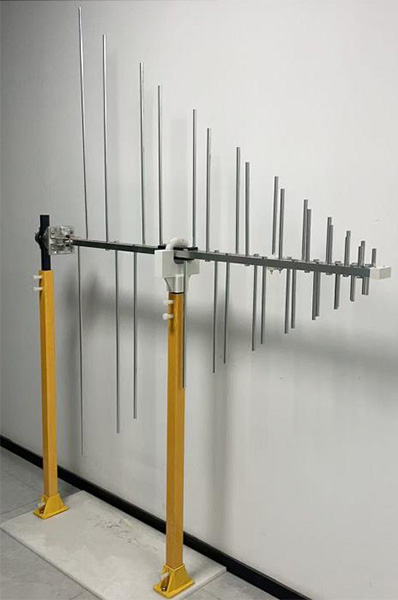
The 1313-2-80M1G log-periodic antenna covers 80 MHz to 1 GHz, with a minimum gain of 6.5 dBi, average gain of 7.5 dBi, and maximum input power of 1000 W. Even with a high-power antenna, the amplifier still needs sufficient output at the frequencies where system efficiency is lowest.
A failure limited to a narrow frequency band is therefore often more useful diagnostically than a system that is weak across the entire range.
Forward Power Is Already Near the Amplifier Limit
Another common warning sign is unusually high forward power during field calibration.
Suppose most frequencies require 30–60 W to produce the target field, but one part of the band suddenly requires 150 W or more.
If the installed amplifier is rated near that value, there may be almost no remaining power margin.
During actual testing, the required power can increase because of:
* Field-uniformity correction
* Antenna polarization
* Temperature
* Cable condition
* Chamber loading
* Frequency-dependent mismatch
A radiated immunity system should not normally depend on the amplifier operating at its absolute maximum output across a significant part of the test range.
When the calibration table repeatedly approaches the amplifier’s maximum usable power, the system is undersized even if it can technically reach the field during calibration.
Increasing Input Drive No Longer Produces a Proportional Increase in Output
RF amplifiers are linear only within a certain operating range.
As the amplifier approaches compression, additional input drive produces progressively less increase in output power.
This can be seen during testing when:
1. RF generator output is increased.
2. Amplifier input rises.
3. Forward power increases only slightly.
4. Field strength barely changes.
The amplifier may be approaching its 1 dB compression point or saturation region.
This condition is important because EMC immunity tests often use amplitude-modulated RF signals. Operating too close to saturation can distort the modulation waveform and increase harmonic content.
The system may therefore have a nominal output-power specification that appears sufficient while its usable linear power is inadequate for the test.
When selecting equipment, linear output power and compression performance are more meaningful than saturated power alone.
Field Strength Becomes Unstable at High Power
A test system with little RF power margin may produce an unstable field near its maximum operating level.
The field probe reading may:
* Rise and fall repeatedly
* Take a long time to stabilize
* Drop after several seconds
* Change more than expected between frequency steps
One possible cause is amplifier thermal behavior.
High-power RF amplifiers generate substantial heat. When operated continuously near maximum output, internal protection or gain-control circuits may reduce output as temperature rises.
Field instability can also result from:
* Amplifier compression
* Excessive reflected power
* Connector heating
* RF switch heating
* Cable loss changing with temperature
This is why a system that passes a short field calibration may still encounter problems during a long automated immunity sweep.
Adequate amplifier headroom improves both field strength and field stability.
The Amplifier Enters Foldback or Protection Mode
Many RF power amplifiers include protection against excessive reflected power.
If antenna mismatch becomes too high, the amplifier may automatically reduce its output to protect the final stage.
This is often called output foldback.
Typical symptoms include:
* Forward power suddenly dropping
* Reflected-power warning
* Amplifier fault indication
* Field strength falling at specific frequencies
* Output recovering after the frequency changes
In this case, installing a larger amplifier may not solve the real problem.
The antenna VSWR and RF path should be checked first.
During radiated immunity testing, poor antenna matching means part of the amplifier output is reflected instead of radiated. Higher VSWR can therefore create both an apparent lack of amplifier power and a protection problem.
The relationship between antenna VSWR and RF power transfer is covered in How Frequency Range, Antenna Factor, VSWR, and Power Handling Affect EMC Antenna Selection.
One Polarization Requires Much More Power
A useful diagnostic clue occurs when horizontal and vertical antenna polarization require very different forward power.
Some difference is normal because antenna position, chamber reflections, and field distribution change with polarization.
However, an unusually large difference should be investigated.
Possible causes include:
* Antenna alignment changing during polarization
* RF cable bending differently
* Cable pulling on the antenna
* Chamber reflection differences
* Incorrect antenna position
* Connector movement
* Limited amplifier margin
If one polarization is already close to the available amplifier limit, the system may fail field-uniformity calibration only in that orientation.
The problem should not immediately be classified as “insufficient amplifier wattage.” First confirm that antenna position and cable routing remain correct after polarization changes.
Only Part of the Test Area Reaches the Required V/m
A system may achieve the required electric field at the center of the test plane but fail at several outer calibration points.
This is a field-uniformity problem, but limited amplifier power can make it impossible to correct.
The test software normally increases forward power until enough calibration points reach the required field level. If the weakest locations still remain below target when the amplifier reaches its limit, additional available power is required—or the antenna/test geometry must be improved.
This is particularly common with:
* Large test areas
* Short antenna distances
* High-gain antennas
* High frequencies
* Large EUTs
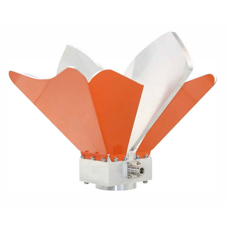
The OBH-08180 broadband dual-ridged horn antenna covers 0.8 GHz to 18 GHz with gain from 5 to 14 dBi. Higher gain improves field-generation efficiency, but the radiation beam becomes an important consideration when a large uniform field area must be illuminated.
More power cannot always compensate for poor beam coverage.
The Required Power Rises Sharply After Changing the RF Cable
A sudden loss of field strength after changing cables, connectors, switches, or adapters often indicates transmission loss rather than an amplifier problem.
The field-strength calculation depends on power delivered to the antenna, not simply power at the amplifier output.
If the amplifier produces 200 W and the complete RF path has 3 dB insertion loss, only approximately half of that power reaches the antenna.
High-frequency RF cables are particularly important because insertion loss increases with frequency.
Check for:
* Longer replacement cable
* Wrong cable type
* Damaged coaxial cable
* Loose connectors
* Excessive adapters
* High-loss RF switches
* Tight cable bends
Before purchasing a larger amplifier, measure or verify the insertion loss of the complete RF path.
Recovering several decibels of cable loss can substantially reduce the required amplifier power.
Calibration Works, but There Is Almost No Power Margin
A system does not need to fail calibration before its amplifier can be considered undersized.
Suppose a 200 W amplifier consistently requires 185–195 W to meet the target field.
Technically, the field can be generated. Practically, the design has little margin for normal variation.
Additional power may later be needed because of:
* Antenna replacement
* Cable aging
* Connector changes
* Field probe uncertainty
* Higher future test levels
* Larger EUT test areas
* Different antenna distances
* Amplifier output variation
Running continuously near the maximum also increases thermal stress and the risk of entering compression.
A better radiated immunity system provides enough reserve that normal field calibration does not depend on the amplifier’s last few watts.
How to Confirm Whether the Amplifier Is Really the Problem
Before deciding that more RF amplifier power is required, compare the complete system.
Check the following in order:
1. Amplifier Output Versus Frequency
Confirm the actual guaranteed output, not only the nominal or saturated rating.
2. Antenna Gain
Low gain means more amplifier power is required to generate the same V/m.
3. Antenna VSWR
High reflected power may prevent available amplifier power from reaching the antenna.
4. RF Path Loss
Measure cable, directional coupler, RF switch, adapter, and connector losses.
5. Antenna Position and Boresight
A directional antenna that is not aimed correctly at the calibration plane wastes RF power.
6. Test Distance
Increasing antenna-to-EUT distance significantly increases the required RF power.
7. Field Uniformity
Determine whether the system lacks total power or simply has poor field distribution.
8. Amplifier Compression and Temperature
Check whether the amplifier output drops when operated continuously at high power.
The complete EMC measurement system should be evaluated before replacing one component.
When a Higher-Power Amplifier Is Actually Needed
Additional RF amplifier power is justified when:
* The existing amplifier cannot reach the calibrated field even with an efficient RF path.
* Forward power remains at or near the amplifier limit across part of the required band.
* Antenna gain and VSWR are already appropriate.
* Cable and switch losses have been minimized.
* Field uniformity is acceptable but the absolute field level remains too low.
* A higher immunity level is required.
* A larger test distance or test area cannot be avoided.
* The current amplifier lacks sufficient linear power for the required modulation.
At that point, the amplifier should be selected according to the worst-case frequency rather than average system performance.
A useful comparison should include amplifier output, antenna gain, VSWR, cable loss, test distance, and required field strength at each frequency.
Insufficient RF power is therefore best identified from the field calibration data, not from amplifier wattage alone. A system that repeatedly reaches its power ceiling, enters compression, shows unstable fields, or cannot satisfy the weakest calibration points is indicating that the available RF power—or the efficiency of the RF path—needs to be improved.