

An EMC chamber project starts long before the shielded panels and RF absorbers arrive on site.
The most successful projects begin with a clear definition of the products to be tested, applicable EMC standards, frequency range, EUT size, test distance, required field strength, and future laboratory expansion. These requirements affect almost every later decision—from chamber dimensions and absorber design to turntable capacity, power filtering, HVAC, and final validation.
Treating an anechoic chamber as a complete engineering project rather than a single piece of test equipment helps avoid expensive changes during installation.
1. Define the EMC Test Scope First
The first stage is to determine exactly what the laboratory needs to test.
Important questions include:
* What types of EUT will be tested?
* What is the maximum EUT size and weight?
* Which EMC standards must be supported?
* Are both radiated emissions and radiated immunity required?
* What frequency range must the chamber cover?
* What is the maximum immunity field strength?
* Will the chamber be used for pre-compliance or accredited compliance testing?
* Are future larger products expected?
A laboratory testing compact consumer electronics has very different requirements from one testing industrial cabinets, automotive systems, UAVs, or large power electronics.
The Practical EMC Lab Setup guide provides a broader overview of how the chamber, measurement instruments, antennas, amplifiers, and accessories should be planned around the actual test scope.
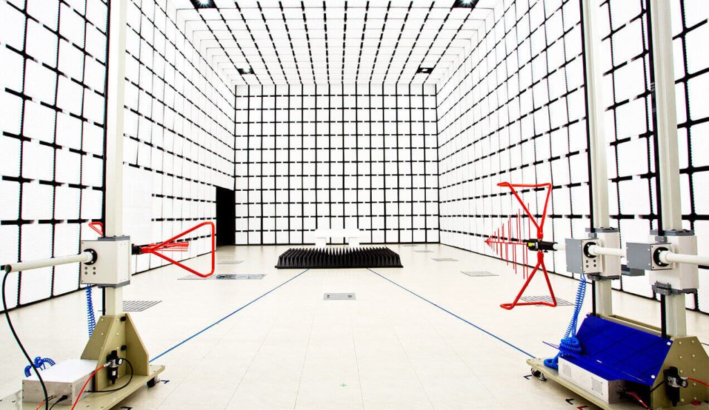
2. Select the Chamber Type and Test Distance
Once the test scope is clear, the next decision is chamber configuration.
Common options include:
* Semi-anechoic chamber
* Fully anechoic chamber
* 3 m test distance
* 5 m test distance
* 10 m test distance
A 3 m chamber is commonly used for small and medium-sized products. Larger industrial equipment may require a 5 m or 10 m chamber because of EUT dimensions, cable layouts, antenna movement, and quiet-zone requirements.
Test distance should not be selected only from available floor space.
The complete rotating EUT, antenna positions, absorber clearance, quiet zone, and required measurement geometry must fit inside the usable test volume.
The article Guidance on Selecting 3M, 5M, and 10M Anechoic Chambers explains these differences in more detail.
3. Check the Building Before Finalizing Chamber Dimensions
The available room dimensions are only the starting point.
A site survey should check:
* Floor dimensions
* Clear ceiling height
* Floor loading capacity
* Building columns and beams
* Existing doors and transport routes
* Equipment access
* Electrical power
* Grounding
* HVAC
* Fire protection
* Cable routes
* Control-room location
Transport access is especially easy to overlook.
Large shielded doors, turntable assemblies, absorber packages, antenna masts, and steel panels must physically reach the installation area.
The chamber also needs service space around or above certain systems. A chamber that fits exactly between building walls may leave insufficient room for installation and maintenance.
For heavy chambers or large turntables, floor structure and foundation requirements should be reviewed before construction begins.
4. Coordinate Civil and Utility Interfaces Early
An EMC chamber depends on several building services, but every penetration through the shielded enclosure has to be controlled.
Typical interfaces include:
* AC power
* Three-phase power
* DC power
* Network connections
* Fiber-optic cables
* Compressed air
* Ventilation
* Cooling
* Fire detection
* Lighting
* Monitoring systems
Normal building cables cannot simply pass through the chamber wall.
Conductive penetrations may require power-line filters, RF filters, shielded feedthroughs, or waveguide-below-cutoff structures.
The same applies to ventilation. Air must enter and leave the chamber without creating a major RF leakage path.
This is why building MEP design and EMC chamber design should be coordinated before installation, not after the shielded enclosure has been completed.
5. Design the Shielded Enclosure and Absorber System Together
The electromagnetic shielded chamber provides isolation between the internal test environment and external electromagnetic signals.
The absorber system controls RF reflections inside that shielded space.
Both systems are required.
A chamber with good shielding but poor absorber performance may have low external noise yet still produce inaccurate radiated measurements because of internal reflections.
A typical semi-anechoic chamber may use:
* Conductive steel shielding
* Ferrite tiles
* Pyramidal RF absorbers
* Conductive ground plane
* Shielded access door
Absorber type, height, and placement depend on chamber geometry and frequency range.
The major structural elements are described in Main Components of a Semi-Anechoic Chamber.
6. Plan the Turntable and Antenna Mast Around the EUT
Mechanical positioning should be defined during chamber design.
For radiated emissions testing, the EUT normally rotates while the receiving antenna changes height and polarization to search for the maximum emission.
Turntable requirements include:
* Diameter
* Load capacity
* Rotation range
* Positioning accuracy
* Speed
* Flush-mounted or raised installation
Antenna mast requirements include:
* Minimum and maximum height
* Antenna payload
* Polarization switching
* Positioning accuracy
* Cable management
The EMC positioning system combines turntable, antenna mast, controller, and optical communication for automated chamber operation.
For large industrial equipment or UAVs, the complete rotating envelope must also be checked against the chamber quiet zone.

7. Define Power, Signal, and Monitoring Interfaces
The EUT may need considerably more than a normal AC outlet.
Before production, confirm requirements for:
* Single-phase AC
* Three-phase AC
* Voltage and current
* DC supplies
* Ethernet
* CAN or other communication lines
* RF connections
* Fiber optics
* Monitoring cameras
* Intercom
* EUT control
Changing these requirements after installation can be difficult because adding a new penetration may affect shielding performance.
It is usually better to provide reasonable future capacity for filters, feedthrough panels, and utility interfaces than to design only for the first EUT.
8. Factory Preparation and Site Installation
Once the design is frozen, chamber components can be manufactured and prepared for installation.
On site, the work typically includes:
1. Shielded enclosure assembly
2. Shielded door installation
3. Electrical bonding and grounding
4. Power filters and feedthrough installation
5. Ventilation system installation
6. Turntable and antenna mast installation
7. Absorber installation
8. Lighting and monitoring installation
9. Control-system integration
Installation quality directly affects final RF performance.
Small gaps in shielded joints, incorrect absorber placement, conductive objects left in the chamber, or poorly installed penetrations can later appear as failures during validation.
For this reason, RF performance should be considered throughout installation rather than only during final acceptance.
9. System Commissioning Before Formal Validation
Before chamber validation begins, the mechanical and electrical systems should be commissioned.
Typical checks include:
* Door operation
* Turntable rotation
* Antenna mast movement
* Polarization switching
* Emergency stop
* Power filters
* Lighting
* HVAC
* Monitoring
* Communication with control software
The RF measurement chain should also be checked, including antennas, cables, receivers, amplifiers, field probes, and positioning control.
Finding basic mechanical or control problems before formal chamber validation avoids repeating expensive RF measurements.
10. Shielding Effectiveness Verification
One of the first RF performance checks is shielding effectiveness.
The purpose is to verify that the enclosure provides sufficient attenuation between the external and internal electromagnetic environments.
Particular attention is normally required around:
* Shielded doors
* Panel joints
* Power filters
* Ventilation panels
* Cable penetrations
A shielding problem should be corrected before chamber site-performance testing, because excessive external signals can affect later measurements.
11. NSA and SVSWR Validation
For radiated emissions, chamber performance must be validated across the intended measurement range.
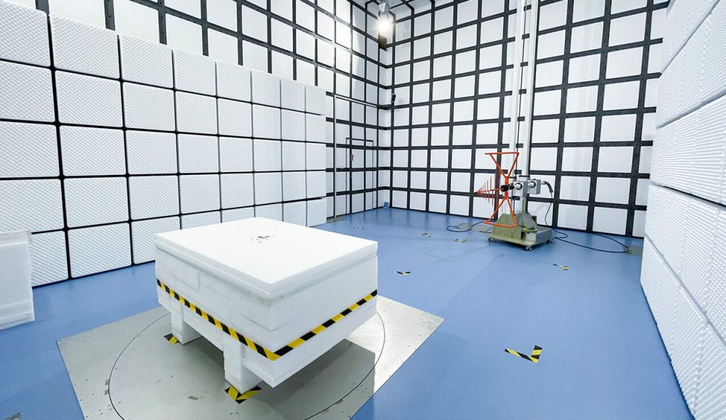
Normalized Site Attenuation (NSA) is commonly used from approximately 30 MHz to 1 GHz. It compares the measured site attenuation with the theoretical reference behavior.
SVSWR is used mainly above 1 GHz to evaluate high-frequency reflections within the test volume.
For the Standard 3m Method Anechoic Chamber, typical performance targets include:
* NSA deviation within ±4 dB
* SVSWR ≤ 6 dB
These tests evaluate the completed chamber—not just the absorber material.
Doors, turntables, antenna masts, cameras, lighting, feedthrough panels, and other structures can all influence the result.
12. Radiated Immunity Field Uniformity
A chamber intended for radiated immunity testing also requires field calibration.
The RF amplifier and transmitting antenna generate the specified field while a field probe measures the test area.
The objective is to verify that the EUT will be exposed to a sufficiently uniform electromagnetic field.
IEC 61000-4-3 defines the radiated RF immunity test framework, including characterization of the test field. The chamber, transmitting antenna, amplifier power, antenna distance, and absorber performance all contribute to the final result.
The differences between NSA, SVSWR, and field uniformity are explained in Key Anechoic Chamber Performance Indicators.
13. Acceptance Documentation and Training
An EMC chamber project should not end when the final validation measurement passes.
The handover package should clearly document:
* Chamber configuration
* Drawings
* Installed interfaces
* Equipment list
* Validation results
* Calibration records
* Operating instructions
* Safety procedures
* Maintenance requirements
Operators should also understand how to use the turntable, antenna mast, filters, doors, monitoring systems, and EMC test equipment without changing the validated test configuration.
Future maintenance matters as well. Door contacts, RF cables, absorbers, connectors, moving positioning equipment, and filters should be inspected periodically.
A successful EMC chamber project therefore moves through a connected sequence:
Test Requirements → Site Planning → Chamber Design → Interface Coordination → Installation → Commissioning → RF Validation → Handover
Skipping decisions at the beginning usually creates more difficult and expensive problems near the end. Defining the test scope and building interfaces before manufacturing starts gives the project the best chance of reaching final NSA, SVSWR, shielding, and field-uniformity requirements without major rework.
Project-Planning Checklist
Before freezing the EMC chamber design, confirm:
* Applicable EMC standards and test methods
* Required emissions and immunity frequency ranges
* Maximum EUT dimensions and weight
* Required test distance: 3 m, 5 m, or 10 m
* Chamber type: semi-anechoic or fully anechoic
* Required quiet-zone and field-uniformity area
* Maximum radiated immunity field strength
* Turntable diameter and load capacity
* Antenna mast height, payload, and polarization
* AC, DC, and three-phase EUT power requirements
* Signal, RF, fiber, and monitoring interfaces
* HVAC and heat-load requirements
* Shielded-door dimensions and equipment access route
* Building floor load and clear ceiling height
* Chamber installation and maintenance clearance
* Required NSA, SVSWR, shielding, and field-uniformity targets
* Control software and positioning-system integration
* Validation, calibration, documentation, and operator-training scope
* Future expansion for larger EUTs or higher test frequencies










