

Automotive electronic components operate in one of the most demanding electromagnetic environments. ECUs, battery management systems, ADAS modules, infotainment units, DC/DC converters, onboard chargers, sensors, and communication modules must operate reliably while sharing a vehicle with high-current switching systems, motors, wireless transmitters, and long wiring harnesses.
Antennas are therefore a critical part of automotive EMC testing.
They are used both to measure RF emissions generated by automotive components and to generate controlled electromagnetic fields during immunity testing.
The correct antenna depends on the test method, frequency range, required field strength, chamber geometry, and whether the antenna is being used as a receiver or transmitter.
Automotive EMC Testing Uses Different Antennas for Different Tasks
There is no single antenna that is ideal for every automotive EMC test.
Component-level testing may include:
– Radiated emissions
– Radiated immunity
– Low-frequency magnetic-field measurements
– High-field RF immunity
– Broadband pre-compliance measurements
Standards such as CISPR 25 are widely used for automotive component emissions, while the ISO 11452 series covers immunity of vehicle electronic components to electromagnetic disturbances.
The complete test requirement should therefore be established before selecting the antenna.
For an overview of automotive test requirements, see EMC Testing Requirements for Automotive Industry.
Biconical Antennas for Lower RF Frequencies
Biconical antennas are commonly used in the lower portion of the radiated EMC frequency range.
Their broad radiation pattern and relatively simple structure make them useful for emissions measurements and, with suitable power handling, RF immunity applications.
Typical advantages include:
– Wide beamwidth
– Broadband operation
– Linear polarization
– Predictable antenna factor
– Suitable receiving performance
– Availability of high-power versions
At lower frequencies, antenna efficiency becomes more difficult because the wavelength is long relative to the physical dimensions of the antenna.
For immunity testing, this can mean that more RF amplifier power is needed to generate the required electric field.
A biconical antenna may therefore be selected not only by frequency coverage but also by:
– VSWR
– Maximum input power
– Antenna gain
– Chamber dimensions
– Required field strength
For high-field automotive immunity testing, antenna and RF amplifier selection should always be evaluated together.
Log-Periodic Antennas for Broadband Automotive EMC Testing
Log-periodic antennas are widely used in automotive component EMC because they provide relatively stable broadband performance over a wide frequency range.
They can be used for both:
– Radiated emissions measurements
– Radiated immunity field generation
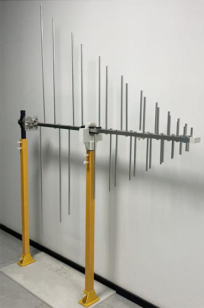
The 1313-2-80M1G Log Periodic Antenna covers 80 MHz to 1 GHz and is designed for high-intensity RF field generation as well as receiving applications.
Its broadband behavior makes it useful for automotive immunity systems where frequent antenna changes would otherwise slow down the test.
Important log-periodic antenna parameters include:
– Frequency range
– Gain
– Gain flatness
– VSWR
– Beamwidth
– Power handling
– Polarization
– Calibration data
For emissions testing, antenna factor and calibration accuracy are particularly important.
For immunity testing, gain and power handling become more important because the antenna must convert amplifier output into the required field strength.
## Wideband Log-Periodic Antennas Can Reduce Antenna Changes
Modern automotive EMC tests extend well beyond traditional VHF frequencies.
Using a wider-band antenna can reduce the number of physical antenna changes during a test sequence.
For example, the 1313-2-700M10G Log Periodic Antenna covers 700 MHz to 10 GHz and is designed for applications including ISO 11452-2 radiated immunity testing.
A wideband antenna can simplify:
– Test automation
– Field calibration
– RF switching
– Antenna positioning
– Chamber setup
However, frequency coverage alone should not determine antenna selection.
Antenna gain, beamwidth, VSWR, and available amplifier power still need to be checked across the complete frequency range.
An antenna that covers 700 MHz to 10 GHz electrically may require very different RF power at 800 MHz and 8 GHz to generate the same test field.
Dual-Ridged Horn Antennas for Higher Frequencies
As automotive electronics use faster processors, high-speed communication, radar, wireless connectivity, and advanced driver-assistance systems, high-frequency EMC testing becomes increasingly important.
Dual-ridged horn antennas are commonly used in this range because they combine:
– Broad frequency coverage
– Directional radiation
– Useful antenna gain
– Relatively low VSWR
– High RF power capability
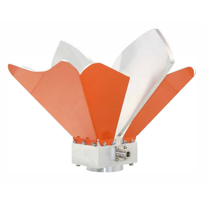
The OBH-08180 Broadband Dual-Ridged Horn Antenna covers 0.8 GHz to 18 GHz and provides increasing gain across the microwave range.
For automotive component immunity testing, the directional gain of a horn antenna helps convert RF amplifier power into higher field strength at the EUT.
This becomes especially important when the required test level is high.
However, higher antenna gain also means that beamwidth must be considered carefully.
The generated field must cover the required EUT and wiring-harness test area rather than only producing a high field at the center point.
Antenna Gain Matters in Automotive Immunity Testing
Automotive component immunity testing can require much higher RF field strengths than many commercial IEC immunity applications.
Generating these fields efficiently depends on the combination of:
Amplifier Power + Antenna Gain + Test Distance
A higher-gain antenna can reduce the amount of RF power required to achieve a given V/m level.
But the antenna must still provide sufficient beam coverage and field uniformity.
This is why selecting the highest-gain antenna is not automatically the best solution.
The complete design should consider:
– Required field strength
– Test distance
– EUT dimensions
– Harness layout
– Antenna gain
– Beamwidth
– Cable loss
– Antenna VSWR
– RF amplifier output
The relationship is discussed in How Amplifier Power, Antenna Gain, and Test Distance Determine Field Strength.
Loop Antennas for Low-Frequency Magnetic Fields
Automotive EMC testing is not limited to electric-field measurements at VHF and microwave frequencies.
Low-frequency electronic and power systems can generate significant magnetic fields.
Examples include:
– DC/DC converters
– Traction inverter systems
– Battery switching circuits
– High-current wiring
– Switching power supplies
– Electric motors and associated electronics
Loop antennas are used where the magnetic component of the electromagnetic field needs to be measured.
The 1313 Series Loop Antenna covers 9 kHz to 30 MHz and is designed for low-frequency magnetic-field measurement.
Compared with a log-periodic or horn antenna, a loop antenna responds primarily to the magnetic field rather than being optimized for higher-frequency far-field electric-field measurements.
This makes it useful when investigating low-frequency noise sources around automotive electronic systems.
Receiving and Transmitting Antennas Have Different Priorities
The same general antenna type may sometimes be used for emissions and immunity, but the selection priorities are different.
For automotive radiated emissions testing, important characteristics include:
– Antenna factor
– Calibration accuracy
– Sensitivity
– Frequency coverage
– Low measurement uncertainty
– Stable polarization characteristics
For automotive radiated immunity testing, the priorities shift toward:
– Antenna gain
– Power handling
– VSWR
– Beamwidth
– Field-generation efficiency
– Thermal performance at high RF power
This distinction matters when specifying an automotive EMC laboratory.
An antenna that performs very well as a calibrated receiving antenna is not necessarily the most efficient choice for generating a 100 V/m or higher immunity field.
Antenna Positioning Is Part of the Test System
A technically suitable antenna can still produce poor results if it is positioned incorrectly.
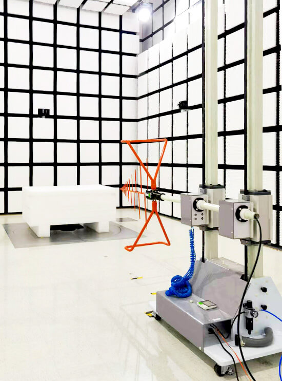
Automotive component tests often use an absorber-lined shielded enclosure with a defined EUT, wiring harness, ground plane, antenna position, and test distance.
Antenna height, orientation, polarization, and boresight should therefore be repeatable.
For immunity testing, the transmitting antenna should illuminate the required test area correctly.
For emissions testing, antenna position must follow the applicable measurement geometry.
The EMC positioning system provides controlled antenna positioning and polarization together with turntable control for chamber-based EMC testing.
For compact automotive component setups, the exact mechanical arrangement may differ from conventional 3 m equipment testing, so the positioning system should be designed around the automotive test bench and chamber configuration.
Automotive Wiring Harnesses Affect Antenna Selection
One feature that distinguishes automotive component testing from many conventional electronic-product tests is the importance of the wiring harness.
The harness can behave as:
– A receiving structure
– A radiating structure
– A coupling path into the ECU
– A path for common-mode RF currents
As a result, the antenna is often exposing or measuring not only the electronic module itself but also the EUT-plus-harness system.
Harness length, height above the ground plane, routing, termination, and support structure can all affect EMC results.
This is particularly important for ECUs and Battery Management Systems, where multiple power and communication lines may be connected simultaneously.
Antenna beamwidth and placement should therefore cover the relevant portion of the complete test setup.
Selecting Antennas for an Automotive EMC Laboratory
A practical automotive component EMC laboratory may use several antenna types rather than one universal broadband antenna.
A typical strategy is to combine:
– Loop antennas for low-frequency magnetic-field measurements
– Biconical antennas for lower RF bands
– Log-periodic antennas for broadband VHF/UHF testing
– Dual-ridged horn antennas for microwave and higher-frequency testing
The exact frequency transitions depend on the applicable standard, available amplifier system, chamber geometry, and required field strength.
Before selecting an automotive EMC test antenna, check:
– Applicable CISPR, ISO, or OEM test method
– Frequency range
– Emissions or immunity application
– Required field strength
– Antenna factor
– Antenna gain
– VSWR
– Maximum input power
– Beamwidth
– Calibration requirements
– Test distance
– EUT and harness dimensions
– Available RF amplifier power
For broader antenna-selection criteria, see How Frequency Range, Antenna Factor, VSWR, and Power Handling Affect EMC Antenna Selection.
Automotive EMC antenna selection should ultimately be based on the complete test configuration. The antenna, RF amplifier, chamber, ground plane, wiring harness, and test distance all affect whether the measurement or immunity field represents the conditions required by the automotive test method.










