

In radiated immunity testing, the electric field applied to the equipment under test is not determined by RF amplifier power alone.
The achievable field strength depends on three main factors: RF power delivered to the antenna, antenna gain, and the distance between the transmitting antenna and the test area.
These parameters are closely related. Increasing amplifier power can raise the field strength, but changing antenna gain or test distance may have an equally important effect. This is why radiated immunity systems should be designed as a complete RF chain rather than by selecting an amplifier based only on wattage.
A typical IEC 61000-4-3 radiated immunity test system includes an RF signal generator, RF power amplifier, directional coupler, transmitting antenna, field probe, anechoic chamber, and test control software.
The Basic Field Strength Relationship
For an initial far-field estimate, electric field strength can be expressed as:
E = √(30 × P × G) / r
where:
* E = electric field strength in V/m
* P = RF power delivered to the antenna in watts
* G = antenna gain as a linear ratio
* r = antenna-to-test-area distance in meters
If antenna gain is given in dBi, it must first be converted to a linear value:
G = 10^(Gain in dBi / 10)
For example, an antenna with 7.5 dBi gain has a linear gain of approximately 5.62.
This equation is useful for estimating RF power requirements during EMC system design. However, it assumes ideal free-space conditions. Actual power requirements inside an anechoic or semi-anechoic chamber must be confirmed through field calibration.
How Amplifier Power Affects Field Strength
Electric field strength increases with the square root of RF power.
This means that doubling the amplifier power does not double the field strength.
If antenna gain and test distance remain unchanged:
* 2× RF power gives approximately 1.41× field strength.
* 4× RF power gives approximately 2× field strength.
* 9× RF power gives approximately 3× field strength.
This relationship becomes important when increasing a radiated immunity test level.
If a system requires 50 W at the antenna to generate 10 V/m, approximately 200 W would theoretically be required to generate 20 V/m under the same conditions.
Reaching 30 V/m instead of 10 V/m would require approximately nine times the RF power.
This is one reason why high-field EMC immunity systems can require amplifiers rated at several hundred watts or more.
More amplifier power is useful, but it is often expensive and may also increase cooling requirements, reflected-power stress, cable power ratings, and antenna power-handling requirements.
How Antenna Gain Changes the Power Requirement
Antenna gain describes how effectively the antenna directs RF energy toward the test area.
For the same amplifier output, a higher-gain antenna can generally produce a stronger field in its main beam.
The 1313-2-80M1G log-periodic antenna covers 80 MHz to 1 GHz and has an average gain of approximately 7.5 dBi. It is designed for both EMC measurement and high-intensity RF field generation.
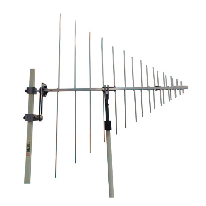
Using the simplified relationship, an antenna with 7.5 dBi gain requires significantly less power than a low-gain antenna to generate the same field at the same distance.
A gain increase of approximately 3 dB corresponds to roughly twice the linear antenna gain.
In practical terms:
* +3 dB antenna gain can theoretically reduce required RF power by about half.
* +6 dB antenna gain can reduce required power to approximately one quarter.
* A 3 dB reduction in gain may require about twice the RF power.
This is why selecting the correct EMC antenna can sometimes be more effective than simply installing a larger amplifier.
However, antenna gain cannot be considered by itself.
Higher gain usually means a narrower radiation beam. During radiated immunity testing, the electromagnetic field must cover a defined test area rather than only one point.
A high-gain antenna may produce excellent field strength in the center of the test area but insufficient field strength toward the edges. The antenna gain, beamwidth, EUT size, and field-uniformity requirement must therefore be evaluated together.
Why Test Distance Matters
Test distance has a strong effect on field strength.
In the simplified far-field relationship, field strength decreases approximately in proportion to distance.
If the antenna-to-EUT distance doubles while power and antenna gain remain unchanged, the field strength falls to approximately half.
Maintaining the same field strength at twice the distance requires approximately four times the RF power.
For example, if a system requires 100 W to achieve a target field at 3 meters, a similar system may theoretically require around 400 W at 6 meters.
This relationship is particularly important when designing larger EMC chambers for:
* Industrial equipment
* Electrical cabinets
* Automotive systems
* Large medical equipment
* UAV and drone systems
* Power conversion equipment
A larger test distance may make it easier to illuminate a large EUT uniformly, but the increased RF power requirement can significantly affect amplifier size and overall system cost.
Test distance should therefore be considered when the EMC chamber and RF immunity system are first designed, not after the amplifier has already been selected.
Antenna Gain Changes with Frequency
A broadband EMC antenna does not provide the same gain across its entire operating range.
For example, the OBH-08180 broadband dual-ridged horn antenna covers 0.8 GHz to 18 GHz, with gain increasing across the frequency range.
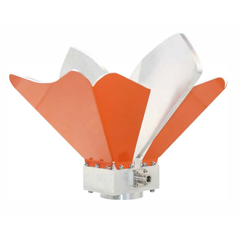
At frequencies where antenna gain is higher, the same RF amplifier can produce a stronger electric field. At frequencies where gain is lower, more RF power is required.
This creates one of the common challenges in broadband radiated immunity testing.
An amplifier may have more than enough power at 5 GHz but struggle to reach the required field at a lower frequency where:
* Antenna gain is lower
* Antenna VSWR is higher
* Cable loss is greater
* Chamber field uniformity is poorer
The RF immunity system should therefore be sized for the difficult frequency points rather than for the average antenna gain.
This is also why the frequency range, gain, VSWR, and power handling of an EMC antenna should be reviewed together.
RF Cable Loss Reduces Available Antenna Power
The field-strength equation uses the RF power that actually reaches the antenna.
The rated output of the amplifier may be significantly higher than the antenna input power because the RF signal passes through other components before reaching the antenna.
A typical RF path may include:
* Coaxial cable
* Directional coupler
* RF switch
* Connectors
* Adapters
* Chamber feedthroughs
Each component introduces insertion loss.
For example, if the complete transmission path has 3 dB loss, only about half of the amplifier output power reaches the antenna.
A 200 W amplifier would therefore deliver approximately 100 W after 3 dB of total loss.
Cable loss becomes particularly important at microwave frequencies. A cable that performs well below 1 GHz may introduce much greater attenuation at 6 GHz, 10 GHz, or 18 GHz.
Using shorter low-loss RF cables and minimizing unnecessary adapters can sometimes increase field strength without changing the amplifier.
For accurate system sizing, use the expected power at the antenna input, not simply the amplifier nameplate output.
VSWR and Reflected Power
The antenna also affects how much of the available RF power is converted into radiated energy.
If the antenna impedance does not closely match the 50-ohm RF system, some power is reflected back toward the amplifier.
This mismatch is commonly described by VSWR.
Higher VSWR can result in:
* Less power delivered to the antenna
* Lower electric field strength
* More reflected power
* Amplifier protection or output foldback
* Increased heating
* Reduced system power margin
An amplifier may therefore appear to have sufficient rated power but still fail to generate the required field at frequencies where antenna VSWR is poor.
The complete VSWR curve should be considered when calculating RF immunity power requirements.
A single catalog value such as “VSWR < 2:1 typical” does not show how the antenna behaves at every frequency.
Field Uniformity Changes the Real Requirement
Radiated immunity testing does not normally evaluate the field at only one point.
Before testing the EUT, the electromagnetic field is calibrated across a defined area. A field probe measures the electric field at several positions while the system adjusts the applied RF power.
The power required to satisfy field uniformity may be considerably higher than the theoretical power needed to generate the target field at the center of the antenna beam.
This is particularly important when:
* The antenna has high gain and narrow beamwidth.
* The EUT is large.
* The antenna is close to the test plane.
* The test frequency is high.
* The chamber geometry limits antenna positioning.
Antenna beamwidth and field uniformity are therefore just as important as maximum field strength.
The article Applications of Dual-Ridged Horn Antennas in EMC Testing explains how horn antenna gain and beamwidth affect high-frequency EMC testing.
Why Calculated and Measured Field Strength Differ
The simplified field-strength equation is useful for comparing amplifier, antenna, and test-distance options, but the calculated value rarely matches the final chamber calibration exactly.
The actual result is influenced by:
* Antenna gain variation
* Antenna VSWR
* RF cable loss
* Directional coupler loss
* Chamber reflections
* Absorber performance
* Antenna height and alignment
* Polarization
* Field probe position
* Field-uniformity requirements
For example, an initial calculation may indicate that 20 W should generate the required field. During calibration, the actual system may require 30 W, 50 W, or more at some frequencies.
This difference is normal because the complete EMC chamber does not behave like ideal free space.
The amplifier should therefore include sufficient operating margin rather than being selected so that the calculated requirement is equal to its maximum output.
Using Power, Gain, and Distance During System Design
When a radiated immunity system cannot reach its required field strength, increasing amplifier power is only one possible solution.
The complete setup should be checked for:
* Insufficient amplifier output
* Low antenna gain
* Excessive RF cable loss
* High antenna VSWR
* Incorrect antenna alignment
* Excessive test distance
* Poor field uniformity
* Incorrect antenna selection for that frequency
For example, if the field shortage occurs only near the lower end of a broadband antenna, switching to a different antenna with higher gain in that range may require less investment than installing a much larger amplifier.
Similarly, replacing a high-loss RF cable may recover several decibels of system power.
The best solution is determined by the complete RF path.
Practical Field Strength Planning
Before selecting an RF power amplifier and transmitting antenna, confirm:
* Required field strength in V/m
* Test frequency range
* Antenna-to-EUT distance
* Antenna gain versus frequency
* Antenna beamwidth
* Antenna VSWR
* Cable and RF switch insertion loss
* Amplifier output versus frequency
* Antenna power handling
* Required test area
* EUT dimensions
* Chamber absorber performance
* Required field uniformity
* Available RF power margin
The EMC measurement system should be designed so that the amplifier, antenna, chamber, RF cables, field probe, and control system work together across the complete test range.
Theoretical calculations provide a useful starting point, but the final reference for radiated immunity testing is always the calibrated electric field produced by the complete system.










