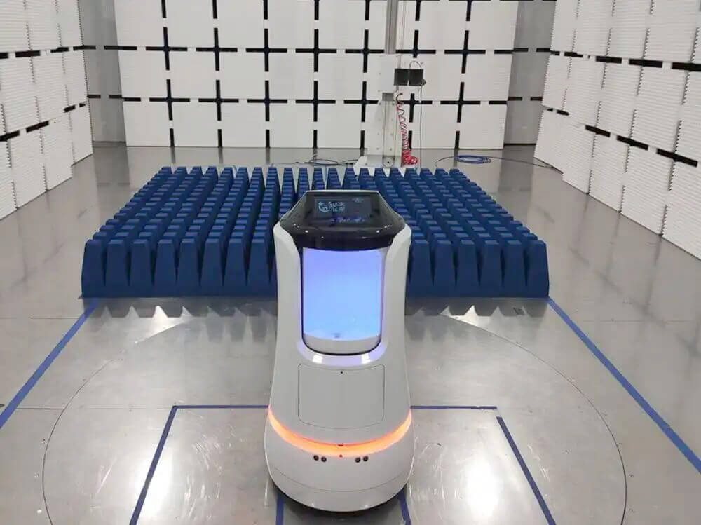
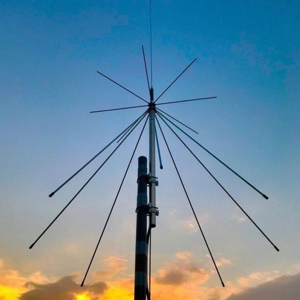
Selecting an RF power amplifier for EMC testing starts with the required test field, not with the highest wattage available.
In a radiated immunity system, the amplifier must provide enough RF power for the transmitting antenna to generate the specified electric field across the required frequency range. The actual power requirement depends on antenna gain, test distance, cable loss, VSWR, chamber performance, modulation, and field uniformity.
This means that a 100 W amplifier may be adequate in one frequency band but insufficient in another, even when the required field strength remains unchanged.
A typical radiated immunity test setup includes an RF signal generator, RF power amplifier, directional coupler, transmitting antenna, field probe, anechoic chamber, and test control software. The amplifier must be selected as part of this complete RF chain rather than as an independent component.
Start with the Required EMC Test Standard
The first step is to define which EMC immunity tests the amplifier must support.
For general radiated RF immunity testing, IEC 61000-4-3 establishes test levels and procedures for exposing electrical and electronic equipment to radiated radio-frequency electromagnetic fields. Product and industry standards then determine the required frequency range and field strength for the equipment being tested.
Other applications may involve:
* Automotive EMC immunity testing
* Military EMC testing
* Aerospace equipment testing
* Industrial electronic equipment
* Medical electrical devices
* Wireless and communication equipment
* High-field RF immunity testing
These applications can require very different field strengths and frequency ranges.
Before selecting an RF amplifier, define:
* Minimum and maximum frequency
* Required field strength in V/m
* Test distance
* Antenna type
* EUT dimensions
* Required field-uniformity area
* Modulation method
* Continuous operating time
Without these values, amplifier wattage alone does not provide enough information for system design.
Frequency Range Is the First Amplifier Selection Limit
An RF power amplifier must cover the complete frequency band assigned to it while providing sufficient output power across that band.
One amplifier rarely provides the same high output power from tens of megahertz to several gigahertz. Wideband EMC immunity systems are therefore commonly divided into several amplifier bands.
For example, a system may use separate amplification for:
* VHF and UHF frequencies
* 1 GHz to several gigahertz
* Higher microwave frequencies
The exact crossover points should be selected together with the antennas.
A broadband antenna can reduce antenna changes, but it does not necessarily eliminate the need for multiple amplifiers. The article How Broadband Antennas Improve EMC Test Efficiency discusses this relationship in more detail.
When reviewing an amplifier datasheet, check the minimum guaranteed output power across the complete band, not only the highest output power shown at one frequency.
Calculate the Required RF Power from the Field Strength
The target field strength is one of the main factors determining amplifier size.
A simplified far-field relationship is:
E ≈ √(30 × P × G) / r
where:
* E = electric field strength in V/m
* P = RF power delivered to the antenna in watts
* G = antenna gain as a linear ratio
* r = antenna-to-test-area distance in meters
The equation is useful for initial amplifier sizing. It also shows why antenna gain matters: a higher-gain antenna generally requires less RF power to generate the same field at the same distance.
However, this calculation should not be used as the final amplifier specification. An actual EMC chamber introduces absorber loss, reflections, cable loss, antenna mismatch, and field-uniformity requirements.
The final system needs enough power to reach the required field during chamber calibration at the worst frequency, not only under ideal theoretical conditions.
Look at Antenna Gain Across the Full Frequency Range
A broadband EMC antenna does not have constant gain.
At some frequencies, the antenna may generate the required field efficiently. At other frequencies, especially near the lower end of its operating range, considerably more amplifier power may be needed.
For example, the 1313-2-80M1G log-periodic antenna covers 80 MHz to 1 GHz and is designed for high-intensity RF field generation.
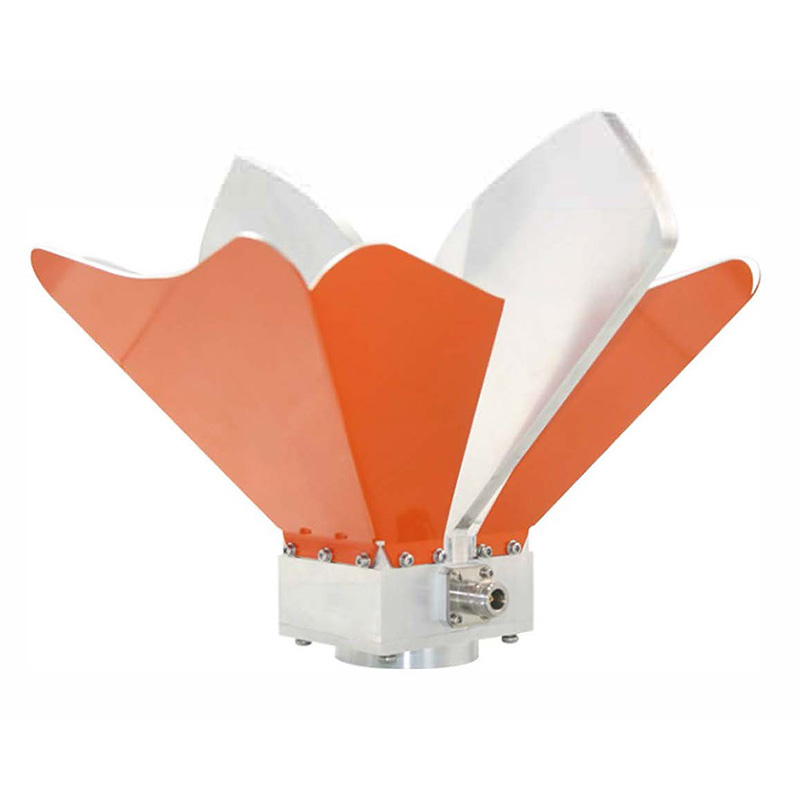
At higher frequencies, a dual-ridged horn antenna can provide more directional gain. The OBH-08180 broadband dual-ridged horn antenna covers 0.8 GHz to 18 GHz, making it suitable for broadband microwave EMC applications. Broadband horn antennas are commonly used above 1 GHz because their directional gain improves RF field-generation efficiency.
Do not size the amplifier from the antenna’s average or maximum gain.
Instead, compare:
* Antenna gain versus frequency
* Amplifier output versus frequency
* Cable loss versus frequency
* Antenna VSWR versus frequency
The point where these factors combine least favorably often determines the required amplifier power.
Rated Power, P1dB, and Saturated Power Are Not the Same
Amplifier specifications may show several different power values.
One of the most important is the 1 dB compression point, or P1dB.
As amplifier input level increases, the output initially rises linearly. Near the upper end of the amplifier’s operating range, the output begins to compress. At P1dB, the actual output is 1 dB below the value expected from ideal linear gain.
Beyond this region, distortion increases and the amplifier eventually approaches saturation.
For EMC immunity testing, it is important to distinguish between:
* Linear output power
* P1dB output power
* Saturated output power
* Maximum survivable output
An amplifier advertised as 200 W saturated power should not automatically be treated as a 200 W linear EMC amplifier.
If the test requires modulation, operating too close to saturation can distort the waveform and alter the applied RF disturbance.
The usable output power should therefore be evaluated under the actual modulation and linearity requirements of the test.
Leave Enough Amplifier Power Margin
Selecting an amplifier that reaches the required field only when operating at its absolute maximum output leaves very little operating margin.
Additional RF power is useful for compensating for:
* Low antenna gain at certain frequencies
* Cable insertion loss
* Directional coupler loss
* Antenna mismatch
* Chamber variation
* Field-uniformity correction
* Amplifier temperature changes
* Cable aging
* Future higher test levels
Power margin also helps prevent the amplifier from operating continuously in compression.
The necessary margin depends on the test system, but the main principle is simple: the required calibrated field should be achievable without forcing the amplifier to operate continuously at its maximum capability.
The relationship between amplifier power, antenna gain, VSWR, and field generation is also covered in Why RF Power Amplifiers Are Essential for Radiated Immunity Testing.
Check Gain and Required Input Drive
Amplifier gain determines how much signal is required from the RF signal generator.
For example, an amplifier with 50 dB gain produces a much larger increase in signal level than one with 30 dB gain.
The signal generator must provide enough drive to reach the required amplifier output, but it must not exceed the amplifier’s maximum input rating.
When several amplifier bands are used, differences in gain can be handled by the EMC control software or signal generator calibration table.
Important amplifier gain specifications include:
* Nominal gain
* Minimum gain
* Gain flatness
* Gain variation with temperature
* Input power required for rated output
Large gain variations across the frequency range increase the amount of correction required during field calibration.
VSWR Tolerance and Reflected Power Protection
The RF antenna does not present a perfect 50-ohm load at every frequency.
As antenna VSWR increases, part of the forward power is reflected toward the RF amplifier.
This can reduce the power delivered to the antenna and increase stress on the amplifier output stage.
An EMC power amplifier should therefore have suitable protection against:
* High reflected power
* Open-circuit load
* Short-circuit load
* Excessive temperature
* Excessive input drive
Some amplifiers reduce output automatically when reflected power becomes too high. This protects the amplifier but may also prevent the test system from reaching the required field strength.
Before increasing amplifier wattage, check whether high antenna VSWR is actually causing the field-strength problem.
The article How Frequency Range, Antenna Factor, VSWR, and Power Handling Affect EMC Antenna Selection explains how antenna mismatch affects RF power transfer.
Include RF Cable and Switch Losses
Amplifier output power is not the same as power delivered to the antenna.
Between the amplifier and antenna, the RF signal may pass through:
* Coaxial cable
* Directional coupler
* RF switch
* Adapter
* Connector
* Bulkhead feedthrough
Every component introduces insertion loss.
This becomes increasingly important at higher frequencies.
If the total RF path has 3 dB loss, approximately half of the amplifier power is lost before reaching the antenna. A nominal 200 W amplifier would therefore deliver only about 100 W after that amount of transmission loss.
For high-frequency EMC immunity systems, reducing cable length and using low-loss coaxial cable can sometimes be more effective than simply purchasing a substantially larger amplifier.
The amplifier calculation should therefore be based on:
Required power at antenna input + total RF transmission loss
rather than amplifier nameplate power alone.
Check Harmonic Performance
RF power amplifiers generate harmonic signals, especially as they approach compression.
During radiated immunity testing, excessive harmonics can create electromagnetic fields at frequencies other than the intended test frequency.
This can make it difficult to determine which frequency is actually causing EUT malfunction.
Amplifier harmonic performance is especially important when:
* High output power is required
* The antenna also operates efficiently at harmonic frequencies
* The amplifier is driven near compression
* The EUT is highly frequency-sensitive
Filtering may be required in some high-power test systems to reduce unwanted harmonic energy.
The amplifier datasheet should therefore be checked for harmonic distortion as well as fundamental output power.
Consider CW and Modulated Power Ratings
EMC immunity tests may use continuous-wave RF with amplitude modulation or another specified modulation method.
The amplifier must support the required waveform for the complete test duration.
Check whether the published amplifier power is specified for:
* Continuous wave
* Pulsed operation
* Peak power
* Average power
* Modulated signals
A high peak-power rating does not necessarily mean that the amplifier can deliver the same power continuously throughout a long immunity sweep.
For an EMC laboratory, continuous output capability and thermal stability are usually more useful specifications than a short-duration peak number.
Cooling Becomes Important at High RF Power
High-power RF amplifiers generate substantial heat.
During automated radiated immunity testing, the amplifier may operate for long periods while the software steps through frequency and monitors EUT performance.
The amplifier installation should provide:
* Adequate ventilation
* Clear air intake and exhaust
* Suitable rack spacing
* Controlled room temperature
* Over-temperature protection
* Continuous cooling during long sweeps
Thermal performance can affect gain and maximum available output power.
An amplifier that reaches the target field during a short calibration may behave differently after extended high-power operation if cooling is inadequate.
Field Calibration Is the Final Check
The final answer to whether an amplifier is large enough comes from the actual field calibration.
During calibration, an electric field probe is placed at defined points within the test area. The system adjusts forward RF power at each frequency until the required field strength is achieved.
The calibration table records how much power is needed across the frequency range.
This immediately reveals frequencies where the system has limited power margin because of:
* Reduced antenna gain
* Higher VSWR
* Increased cable loss
* Chamber behavior
* Field-uniformity requirements
Theoretical calculations are useful during equipment selection, but the calibrated test field is what determines whether the complete system can perform the required radiated immunity test.
One Large Amplifier or Several Smaller Amplifiers?
Using one broadband RF amplifier sounds simpler, but it is not always the best EMC system configuration.
A single wideband amplifier may provide:
* Simpler RF switching
* Fewer system components
* Easier automation
* Less rack space
Several frequency-specific amplifiers may provide:
* Higher output power
* Better efficiency
* Better linearity
* Lower cost per watt
* More useful power at difficult frequencies
* Easier future upgrades
For a broad immunity range, dividing the system into several amplifier and antenna bands is often more practical.
The crossover frequencies should be chosen where the combination of amplifier output and antenna performance gives the best field-generation efficiency.
Practical RF Power Amplifier Selection Checklist
Before selecting an RF power amplifier for EMC testing, confirm:
* Applicable EMC standard
* Required frequency range
* Required field strength
* Antenna-to-EUT distance
* Antenna gain across the full band
* Antenna VSWR
* Required power at the antenna input
* Cable and RF switch insertion loss
* Continuous output power
* P1dB output
* Saturated output power
* Amplifier gain and gain flatness
* Required signal-generator drive
* Harmonic performance
* Modulation compatibility
* Reflected-power tolerance
* Cooling requirements
* Remote-control interface
* Power monitoring capability
* Required operating margin
* Possibility of future higher field-strength tests
Amplifier selection should be completed together with the transmitting antenna and chamber design. The EMC measurement system provides the wider system context, while How to Choose EMC Antennas for EMC Testing covers antenna selection across different EMC frequency ranges.