EMC testing becomes mechanically more demanding when the equipment under test is large, heavy, irregularly shaped, or connected to long cables and auxiliary equipment.
This is particularly relevant for large industrial equipment, UAVs, drone systems, power conversion equipment, cabinets, and complete electromechanical assemblies.
For these products, the EMC positioning system is not simply a turntable and antenna mast added to the chamber. Turntable diameter, load capacity, antenna travel, cable routing, rotation clearance, positioning accuracy, and safety control all become part of the test-system design.
A standard anechoic chamber positioning system may be suitable for many medium-sized products, but large equipment and UAV EMC testing often require additional mechanical and spatial evaluation.
Start with the Complete EUT Test Envelope
The first parameter to define is not only the physical size of the product.
The complete EUT test envelope may include:
* EUT body
* Landing gear or support frame
* Battery system
* External power supply
* Cable harnesses
* Communication cables
* Loads and simulators
* Monitoring equipment
* Support fixtures
For UAV EMC testing, the airframe itself may be relatively light, but the full setup can occupy a large horizontal area because of wings, rotors, landing structure, external wiring, or operating-support equipment.
The positioning system must therefore be sized according to the complete rotating footprint, not just the dimensions listed on the product datasheet.
This is especially important when selecting between a 3 m, 5 m, or 10 m anechoic chamber.
Turntable Diameter Must Allow Full Rotation
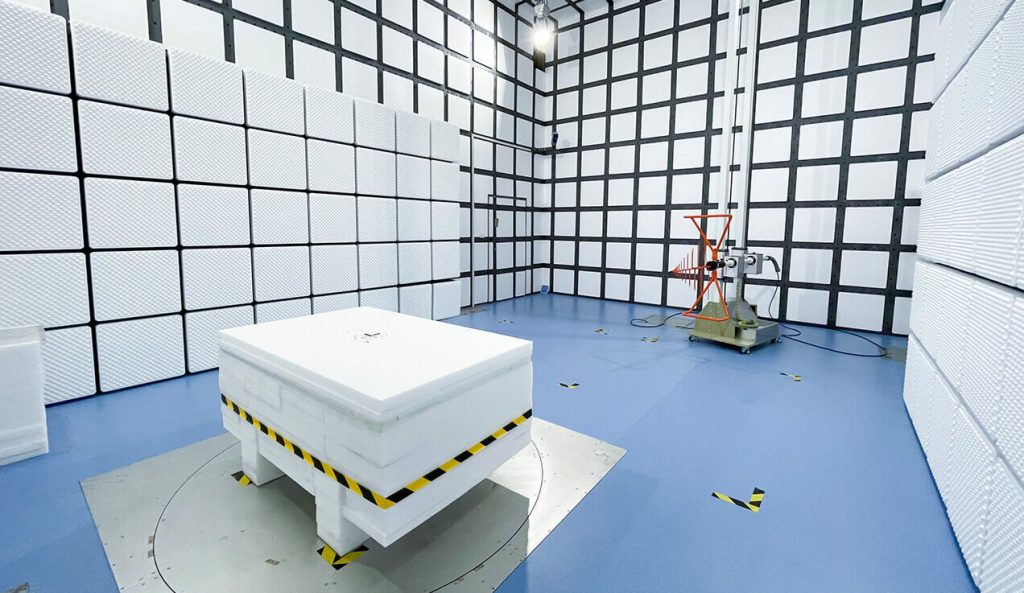
Large equipment requires enough platform area to rotate through the required angles without contacting absorbers, chamber structures, antenna equipment, or cable-support systems.
The standard GETT-2000 configuration on the positioning system page uses a 2 m diameter turntable with 0°–360° rotation.
For a compact industrial controller or electronic cabinet, this may be sufficient.
For a larger UAV or machine, however, the actual rotating envelope may extend well beyond the platform diameter.
The design should consider:
* Maximum EUT width
* Maximum diagonal dimension
* Overhanging components
* Rotating cable radius
* Required clearance from absorbers
* Distance from the EUT to the antenna
* Chamber quiet-zone dimensions
An EUT can physically fit on a platform but still be unsuitable for testing if part of the product moves outside the validated quiet zone during rotation.
Load Capacity Includes Fixtures and Test Accessories
Turntable load capacity should not be calculated from EUT weight alone.
The complete load may include:
* Product weight
* Test table or support structure
* Mounting frame
* Batteries
* Artificial networks
* Cable trays
* Auxiliary loads
* Mechanical fixtures
The standard GETT-2000 turntable has a maximum load of 1.5 t. For heavier industrial equipment, customized positioning systems or floor-level heavy-duty turntables may be required.
Insufficient load capacity can lead to:
* Platform deformation
* Uneven rotation
* Positioning error
* Drive-system overload
* Increased mechanical wear
* Safety risk
For heavy EMC test items, foundation strength and turntable installation method should also be considered as part of chamber planning.
Center of Gravity Matters for Large and Irregular EUTs
Weight alone does not describe the mechanical challenge.
A large cabinet may have a relatively simple center of gravity, while a UAV with wings, rotors, payloads, or asymmetrical equipment may have a much less balanced mass distribution.
An off-center load can create additional stress on:
* Turntable bearings
* Drive motors
* Gear systems
* Support fixtures
The EUT should be positioned as close as practical to the center of rotation.
For tall or narrow equipment, stability during acceleration and deceleration must also be considered.
A positioning system should move smoothly enough that the EUT does not shift relative to its defined test configuration during the scan.
Rotation Speed Must Match the Measurement Process
Higher turntable speed does not always improve EMC test efficiency.
The receiver or spectrum analyzer needs enough time to detect emission peaks while the EUT rotates.
Large equipment may also require slower mechanical movement because of:
* Higher mass
* Greater rotational inertia
* Long external cables
* Fragile fixtures
* Uneven weight distribution
The GETT-2000 standard configuration provides adjustable rotation from approximately 0.5 to 2 rpm.
For large-equipment testing, the appropriate speed should be coordinated with receiver sweep time, detector settings, and test software.
A fast rotation that causes the measurement system to miss a narrow emission maximum is not useful.
Cable Management Becomes a Major Design Issue
Large equipment and UAV systems often use many external connections.
These may include:
* AC or DC power cables
* Ethernet
* CAN bus
* RF cables
* Control lines
* Fiber optics
* Battery cables
* Sensor wiring
When the EUT rotates, these cables must move without:
* Pulling the product off-center
* Changing cable geometry unpredictably
* Twisting excessively
* Contacting absorbers
* Crossing the antenna path
* Creating a trip or mechanical hazard
Cable arrangement is also part of EMC test repeatability.
If cable geometry changes significantly during rotation, the measured radiated emission may change because the cable itself is acting as part of the radiating structure.
For large EUTs, cable routing should therefore be planned together with the turntable rather than after chamber installation.
Antenna Mast Height Must Match the EUT Height
Large equipment also increases antenna-positioning requirements.
In conventional radiated emission testing, the receiving antenna may need to scan vertically to find the maximum signal.
The standard GEAM-4600 antenna mast provides an antenna centerline range of approximately 1 m to 4 m, with ±1 cm height accuracy and automatic 0°/90° polarization switching.
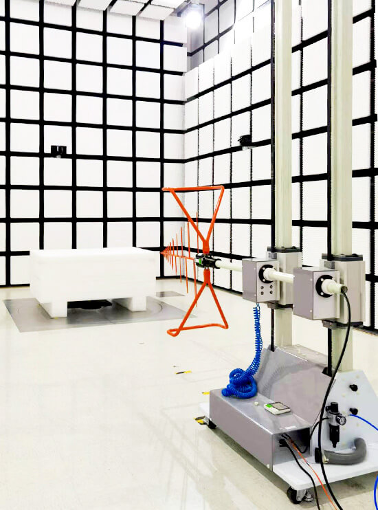
For many standard 3 m chamber applications, this range is sufficient.
However, taller industrial systems or large UAV configurations may require:
* Greater maximum antenna height
* Longer vertical travel
* Higher chamber ceiling
* Larger quiet-zone height
* Improved mast structural rigidity
A large EUT should not automatically be placed in a chamber simply because there is enough floor area.
The vertical geometry must also support the required antenna scan and validated test volume.
Antenna Load and Boresight Must Be Checked
The mast itself also has a payload limit.
The GEAM-4600 standard configuration supports antenna loads up to 10 kg and provides tilt capability for boresight adjustment.
For large-EUT testing, this becomes relevant when using:
* Large broadband antennas
* Heavy horn antennas
* Custom antenna brackets
* Preamplifiers mounted near the antenna
* Additional RF cable support
The antenna should remain correctly aligned throughout the height scan.
A heavy cable pulling on the antenna can change antenna tilt or polarization and reduce repeatability.
For high-frequency UAV EMC testing, accurate boresight becomes particularly important because higher-gain horn antennas can have narrower beamwidth.
Quiet Zone Size Can Limit the Positioning System
The turntable may physically rotate a large UAV, but that does not mean the chamber can validly test it.
The entire EUT should remain within the required validated test region.
The Standard 3 m Method Anechoic Chamber typically uses a smaller quiet zone than larger 5 m or 10 m chamber configurations.
When product dimensions increase, a 5m anechoic chamber can provide more spatial flexibility.
For complete vehicles, large machines, large UAV platforms, or extensive cable arrangements, a 10m anechoic chamber may be more appropriate because of its larger test volume and quiet zone.
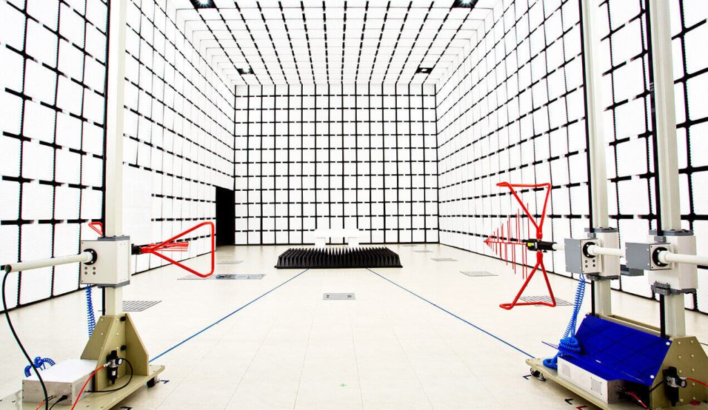
The chamber and positioning system should therefore be selected together.
A larger turntable installed inside a chamber with an insufficient quiet zone does not solve the actual EMC test limitation.
Positioning Accuracy Still Matters on Large Systems
Large equipment can make a positioning error look small physically, but repeatability remains important.
Suppose an emission peak is found at 137°.
After an EMC modification, the engineer may need to return to exactly that orientation to compare the result.
The positioning system should therefore provide repeatable control of:
* Turntable angle
* Antenna height
* Antenna polarization
* Antenna tilt where applicable
The GETT-2000 standard system specifies approximately ±1° angular positioning accuracy, while the GEAM-4600 specifies approximately ±1 cm height-scan accuracy.
These values support repeatable automated testing for many chamber applications.
For unusually large structures, the effect of angular error at the outer edge of the EUT should also be considered because a small angle at the rotation center can translate into larger physical movement at the extremities.
Remote Control and Low-Interference Communication
Large positioning systems should be controlled without adding unnecessary RF interference inside the chamber.
The standard GE positioning system uses polymer optical-fiber communication between the turntable, antenna mast, and controller.
The GEC-3 controller integrates PLC, touchscreen, LAN, USB, RS232, and optical-fiber interfaces for coordinated motion control.
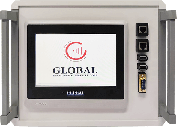
Fiber communication is useful in an EMC chamber because it avoids long conductive communication paths that could introduce unwanted RF coupling.
For automated testing, the controller should also allow the EMC software to record and reproduce:
* EUT angle
* Antenna height
* Polarization
* Test frequency
* Measurement result
This makes troubleshooting and final measurement much more repeatable.
Safety Requirements Increase with EUT Size
Mechanical safety becomes more important as the EUT becomes heavier or physically larger.
A positioning system for large equipment should consider:
* Emergency stop
* Rotation limits
* Collision clearance
* Overload protection
* Cable entanglement
* Door interlock
* Operator exclusion during movement
* Stable EUT mounting
* Controlled acceleration and deceleration
For UAV testing, rotors or propulsion systems may also require special operational controls depending on the intended EUT operating mode.
The EMC test plan should define which systems must be energized and which moving components must remain disabled during radiated testing.
Practical Positioning System Checklist
For large equipment and UAV EMC testing, confirm:
* Complete EUT dimensions
* Total test weight
* Center of gravity
* Turntable diameter
* Maximum turntable load
* Full 360° rotating envelope
* Quiet-zone diameter and height
* Antenna mast travel
* Antenna payload
* Required polarization
* Antenna boresight
* RF and power cable routing
* Rotation speed
* Angular positioning accuracy
* Chamber ceiling height
* Safety clearance
* Remote control and software integration
The same principles discussed in Why EUT Rotation and Antenna Height Scanning Matter in Radiated Emission Testing become more critical as EUT size increases.
For large equipment and UAV EMC testing, the positioning system should be specified from the complete test geometry, not from turntable diameter or load capacity alone.