Active antennas are widely used in EMC measurements where weak electromagnetic signals are difficult to detect with conventional passive antennas. They are particularly useful for low-frequency electric and magnetic field measurements, where a physically compact receiving antenna may produce a very small output voltage.
However, an active antenna is not automatically more accurate than a passive antenna. Its built-in amplifier improves sensitivity under suitable conditions, but it also introduces limitations related to dynamic range, overload, power supply stability, and calibration.
The choice between active and passive antennas should depend on the measurement frequency, field strength, expected interference level, and applicable EMC test method.
What Is an Active Antenna?
An active antenna combines a receiving antenna element with an integrated electronic amplifier or impedance-conversion circuit.
A typical active antenna measurement chain is:
EUT → Active Antenna → RF Cable → EMI Receiver
The amplifier is located close to the antenna element, allowing weak signals to be amplified before they travel through the RF cable.
This arrangement can improve measurement sensitivity, particularly when the antenna element has low output at the frequency being measured.
Common active antenna configurations include:
– Active loop antennas for magnetic field measurements
– Active monopole antennas for low-frequency electric field measurements
– Specialized broadband active receiving antennas
Unlike antennas used for radiated immunity field generation, these active antennas are primarily receiving devices. Their integrated amplifiers are not designed to transmit high RF power.
When Low-Frequency EMC Measurements Benefit from Active Antennas
Active antennas are especially useful at low frequencies, where the relationship between antenna size and wavelength makes efficient reception difficult.
At frequencies such as 9 kHz, 150 kHz, or 1 MHz, the wavelength is much larger than a typical laboratory antenna.
A compact passive antenna may therefore produce only a small voltage in response to a weak electromagnetic field.
Adding a low-noise amplifier can improve the signal-to-noise ratio of the complete measurement system.
Typical applications include:
– Switching power supply emissions
– Industrial control equipment
– Low-frequency communication systems
– Electronic lighting equipment
– Power conversion equipment
– Magnetic field measurements around electrical devices
Active antennas are particularly valuable when the measurement-system noise floor would otherwise limit the detection of weak emissions.
Active Loop Antennas for Magnetic Field Measurements
Loop antennas are commonly used for measuring the magnetic component of electromagnetic disturbances.
Their output is related to the changing magnetic flux through the loop area.
At low frequencies, the voltage induced in a compact loop can be relatively small.
An active loop antenna uses an integrated amplifier to improve usable receiving sensitivity.
The 1313 Series Loop Antenna includes two configurations:
| Model | Antenna Type | Frequency Range |
|---|---|---|
| 1313-1A | Active loop antenna | 9 kHz–30 MHz |
| 1313-1P | Passive loop antenna | 9 kHz–30 MHz |
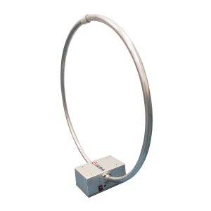
Both models use a 60 cm diameter loop, but their receiving characteristics differ because the active version includes amplification.
The 1313-1A also provides battery-powered operation, a low-battery indicator, and a saturation indicator.
These functions are important because active antenna measurement accuracy depends on the condition of its internal amplifier.
For additional information about loop antenna applications, see Loop Antennas for Low-Frequency Magnetic Field Measurements.
Active Monopole Antennas for Electric Field Measurements
Active monopole antennas are another common choice for low-frequency EMC measurements.
Unlike loop antennas, which respond primarily to magnetic fields, monopole antennas are used to measure the electric-field component.
A short monopole has relatively high source impedance and limited sensitivity at low frequencies.
An active matching circuit or amplifier helps convert the received signal into a form suitable for an EMI receiver.
Active monopole antennas can be useful for:
– Low-frequency radiated emissions
– Electric field investigations
– Electrical equipment measurements
– Broadband interference monitoring
However, antenna selection must follow the applicable test standard.
An active monopole cannot automatically replace a loop antenna because electric-field and magnetic-field measurements represent different quantities.
This distinction is particularly important in the near-field region, where electric and magnetic fields do not necessarily maintain the fixed relationship associated with far-field propagation.
Active vs. Passive Antennas: Which Is Better?
The main advantage of an active antenna is improved weak-signal reception.
A passive antenna, however, has no built-in active amplification stage and generally avoids amplifier-related compression and power supply problems.
| Parameter | Active Antenna | Passive Antenna |
|---|---|---|
| Integrated amplifier | Yes | No |
| Weak-signal sensitivity | Often better | Depends on antenna and receiver |
| Overload risk | Amplifier compression possible | No internal amplifier compression |
| Power requirement | Usually required | Not required |
| Measurement correction | Complete active antenna calibration | Passive antenna calibration |
| Strong-signal suitability | Limited by active-stage dynamic range | Often preferable |
An active antenna is generally more attractive when weak-signal sensitivity is the limiting factor.
A passive antenna can be preferable when emissions are already strong, overload is likely, or the measurement system has sufficient sensitivity without additional amplification.
The correct choice depends on the complete receiving system rather than antenna gain alone.
Why Active Antenna Overload Is a Serious Problem
An active antenna can produce incorrect results if its built-in amplifier is driven into compression.
Strong electromagnetic signals may originate from:
– Nearby broadcast transmitters
– Industrial switching equipment
– Strong EUT emissions
– Pulsed RF disturbances
– Multiple simultaneous interference sources
When the amplifier approaches its compression point, the output no longer increases proportionally with the input.
This can produce:
– Underestimated emission levels
– Harmonic distortion
– Intermodulation products
– Unstable measurement readings
– Reduced measurement repeatability
An overloaded active antenna may still produce a normal-looking receiver trace, making the problem difficult to identify without checking the antenna’s operating condition.
The 1313-1A Active Loop Antenna includes a saturation indicator that warns when the internal amplifier exceeds its specified linear operating range.
If the indicator activates, the measurement should not be treated as accurate until the overload condition has been resolved.
Dynamic Range Matters More Than Gain Alone
A high-gain active antenna is not necessarily the best choice for every EMC measurement.
Dynamic range describes the usable signal range between the noise floor and the maximum level that can be measured without unacceptable distortion.
For weak emissions, low noise is important.
For strong or pulsed emissions, sufficient overload margin becomes equally important.
A system may need to measure a weak disturbance while much stronger signals are present elsewhere in the frequency spectrum.
The active antenna amplifier must handle the combined signal environment, not only the frequency being displayed by the EMI receiver.
This is especially important when measuring impulsive disturbances, whose instantaneous peaks can be significantly higher than their average signal levels.
For these applications, review:
– Antenna sensitivity
– Noise performance
– Dynamic range
– 1 dB compression point
– Maximum measurable field strength
– Overload indication
– Frequency-dependent calibration data
Calibration Must Include the Built-In Amplifier
An active antenna must be calibrated as a complete receiving device.
Its correction data should account for the antenna element and integrated electronics.
For an active magnetic field antenna, the supplied magnetic antenna factor converts the receiver indication into the appropriate magnetic field quantity after the required measurement-chain corrections.
The test software must use the correct calibration data for the specific antenna model.
A common mistake is applying an additional amplifier gain correction when the active antenna’s calibrated factor already includes that gain.
This would produce an incorrect final result.
Calibration accuracy can also be affected by:
– Amplifier gain drift
– Incorrect power supply voltage
– RF cable changes
– Connector problems
– Operation outside the specified frequency range
The wider measurement-chain considerations are covered in Key Factors Affecting EMC Antenna Measurement Accuracy.
Power Supply Stability Affects Measurement Accuracy
Unlike passive antennas, active antennas require electrical power.
The power may be supplied through batteries, an external DC source, or a dedicated bias arrangement.
For battery-powered antennas, declining voltage can change amplifier behavior.
The 1313-1A Active Loop Antenna uses two 18650 batteries in series and includes a low-battery indicator.
If the supply voltage falls below the specified operating level, amplifier gain may change and the antenna calibration factor may no longer represent the actual response.
Before a critical EMC measurement:
– Check battery condition.
– Confirm normal indicator status.
– Verify the specified power supply.
– Inspect the RF output connection.
– Allow any required stabilization time.
These checks are particularly important during long measurement sessions.
When a Passive Antenna Is the Better Choice
Active amplification is not always necessary.
A passive antenna may provide adequate sensitivity when:
– The expected field strength is relatively high.
– The EMI receiver has a sufficiently low noise floor.
– A suitable external low-noise preamplifier is available.
– Strong ambient signals create overload concerns.
– The applicable measurement method requires a particular passive configuration.
For broadband radiated emissions above 30 MHz, calibrated passive biconical, log-periodic, and horn antennas are commonly used.
An external preamplifier can be added when the measurement chain requires additional sensitivity.
The difference is that the amplifier remains a separately configurable component.
The article How RF Cables, Connectors, and Preamplifiers Affect EMC Test Results explains how external preamplifiers influence the receiving system.
Decision Guide: When Should You Use an Active Antenna?
Selecting between an active and passive antenna should start with the measurement requirement rather than the antenna’s advertised gain.
Step 1: Identify the Field Type
– Low-frequency magnetic field: Consider an active or passive loop antenna.
– Low-frequency electric field: Consider an active monopole antenna where the test method permits.
– Higher-frequency radiated emissions: A calibrated passive antenna, with an external preamplifier if needed, is often more suitable.
Step 2: Check Measurement Sensitivity
If the expected emission is close to the measurement-system noise floor, an active antenna may improve sensitivity.
If a passive antenna already provides adequate signal-to-noise ratio, integrated amplification may offer little additional benefit.
Step 3: Evaluate Overload Risk
For strong emissions, pulsed disturbances, or environments with powerful ambient RF signals, check the active antenna’s maximum input capability and dynamic range.
If overload cannot be avoided, a passive antenna may be preferable.
Step 4: Confirm Calibration and Test Requirements
Verify that the selected antenna type is permitted by the applicable EMC standard and that valid antenna-factor calibration data is available.
Step 5: Make the Selection
| Measurement Application | Recommended Antenna |
|---|---|
| Weak low-frequency magnetic fields | Active loop antenna |
| Strong low-frequency magnetic fields | Passive loop antenna |
| Low-frequency electric field measurements | Suitable calibrated active monopole |
| Broadband radiated emissions above 30 MHz | Passive EMC antenna, with optional external preamplification |
The final choice should provide sufficient sensitivity without overload, while meeting the frequency range, field quantity, and calibration requirements of the test.
Practical Active Antenna Selection Checklist
Before choosing an active antenna for EMC measurements, confirm:
– Required frequency range
– Electric or magnetic field measurement
– Applicable EMC standard
– Expected minimum field strength
– Maximum expected signal level
– Antenna noise performance
– Dynamic range and compression point
– Overload indicator availability
– Calibration factor and measurement units
– RF connector and output impedance
– Power supply requirements
– Cable and receiver compatibility
– Measurement distance and antenna orientation
Active antennas are most useful when they improve the sensitivity of a measurement that would otherwise be limited by weak antenna output or receiving-system noise.
However, the best measurement is not necessarily the one with the highest amplification. Adequate dynamic range, stable calibration, correct antenna orientation, and freedom from overload are equally important for reliable EMC results.