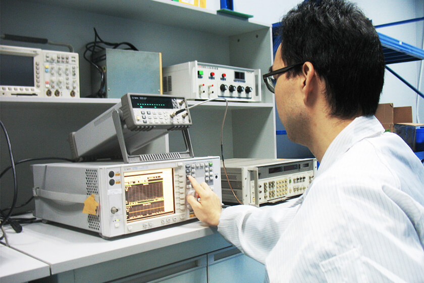
Many products perform normally during development but fail when submitted for formal EMC compliance testing. This situation is common across industrial electronics, wireless communication equipment, automotive modules, medical devices, power electronics, and consumer products.
In most cases, EMC compliance failures are not caused by a single defective component. Instead, they result from interactions between PCB layout, grounding structures, cable routing, shielding effectiveness, and electromagnetic coupling paths that only become visible under standardized EMC test conditions.
Understanding why EMC compliance tests fail can help manufacturers reduce certification costs and improve first-pass success rates.
EMC Compliance Testing Covers More Than Emissions
Many engineers associate EMC compliance with radiated emission testing alone. In reality, EMC certification often includes multiple test categories such as:
* Radiated Emission (RE)
* Conducted Emission (CE)
* Radiated Immunity (RI)
* Conducted Immunity (CI)
* Electrostatic Discharge (ESD)
* Electrical Fast Transient (EFT)
* Surge Immunity
A product may successfully pass one test category while failing another.
For example, equipment that passes CISPR radiated emission limits may still fail IEC 61000-4-3 radiated immunity testing due to RF susceptibility.
Poor PCB Layout Is One of the Most Common Causes
PCB layout decisions directly influence EMC performance.
Common design problems include:
* Long high-speed traces
* Incomplete ground planes
* Poor decoupling capacitor placement
* Excessive loop areas
* Weak chassis grounding
These issues increase both electromagnetic emissions and susceptibility to external RF energy.
Products containing switching power supplies, microcontrollers, RF modules, and high-speed interfaces are particularly sensitive to PCB layout quality.
Conducted Emission Failures
Conducted emission failures frequently occur in:
* Industrial controllers
* Battery chargers
* Inverters
* AC/DC power supplies
* EV charging systems
Typical causes include:
* Weak EMI filtering
* Poor grounding
* High-frequency switching noise
* Improper cable shielding
During compliance testing, engineers commonly use a LISN for conducted emission measurements to evaluate noise transmitted through power lines.
Many conducted emission failures can be traced back to insufficient filter design during product development.
Radiated Emission Problems
Radiated emission testing evaluates electromagnetic energy emitted from a product through free space.
Common failure sources include:
* High-speed digital clocks
* Poor shielding
* Cable radiation
* Switching power electronics
* Improper enclosure bonding
External cables often become unintended antennas, significantly increasing measured emissions.
In many EMC investigations, modifying cable routing produces larger improvements than replacing components.
Radiated Immunity Test Failures
Radiated immunity failures are becoming increasingly common as products integrate wireless communication functions.
Typical failure symptoms include:
* Unexpected reset
* Communication loss
* Sensor instability
* Software malfunction
* Display disturbances
IEC 61000-4-3 testing typically requires:
* RF signal generator
* RF power amplifier
* EMC antenna
* Field probe
* Anechoic chamber
High-field-strength applications often require RF power amplifiers for EMC immunity testing capable of maintaining stable field levels throughout the frequency sweep.
Proper EMC antenna selection also plays a critical role in field uniformity performance.
Shielding Is Often Less Effective Than Expected
Many products use metal enclosures but still fail EMC testing.
Typical shielding problems include:
* Poor seam conductivity
* Connector leakage
* Ground discontinuity
* Ventilation openings
* Improper shield termination
At higher frequencies, even small enclosure gaps can become significant radiation sources.
Shielding performance should always be verified through testing rather than assumed based on enclosure material alone.
EMC Chamber and Test Setup Factors
Not every EMC failure originates from the DUT.
Test setup variables can influence results, including:
* Antenna positioning
* DUT orientation
* Chamber calibration
* Ground plane installation
* Cable arrangement
Organizations establishing in-house EMC capability often implement complete EMC laboratory setup solutions to improve repeatability and reduce measurement uncertainty.
Stable testing environments become increasingly important when evaluating automotive, aerospace, and wireless communication products.
EMC Failures Usually Follow a Predictable Pattern
When engineers review failed EMC reports, the same issues appear repeatedly:
* Poor grounding
* Inadequate filtering
* Weak shielding
* Cable coupling
* PCB layout problems
Successful EMC design begins during product development, not after certification testing has already failed.
Manufacturers that perform pre-compliance EMC testing early in the design cycle typically identify these problems before formal certification, reducing both project risk and redesign cost.