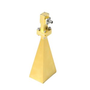
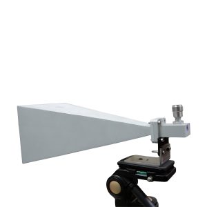
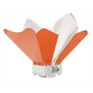
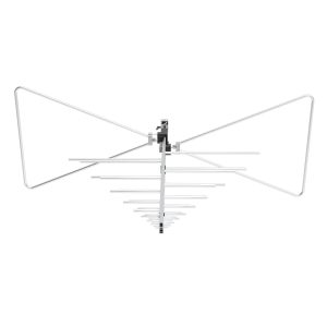
EMC test antennas should be inspected before use, handled by their mounting structures, kept clean and dry, and stored in protective cases when not installed. Particular attention should be paid to antenna elements, RF connectors, mounting hardware, and calibration status.
Physical damage does not always make an antenna unusable. A slightly bent element, loose connector, or damaged balun connection may leave the antenna operational while changing its frequency response, impedance matching, or antenna factor.
For EMC laboratories performing radiated emissions and immunity testing, routine EMC antenna maintenance helps preserve measurement repeatability and reduces the risk of unexpected equipment failures.
Why Proper Antenna Maintenance Matters
EMC antennas are measurement instruments with defined electrical and mechanical characteristics.
Their performance depends on element dimensions, conductor geometry, feed structures, RF connectors, and impedance-matching components.
Mechanical damage can affect different antenna types in different ways:
– Bent biconical elements may change antenna geometry.
– Misaligned log-periodic elements may affect frequency response.
– Damaged horn structures may alter high-frequency performance.
– Deformed loop antennas may change magnetic-field response.
– Active antenna electronics may be affected by power or overload problems.
These issues can influence measured emissions or the field strength generated during immunity testing.
Antenna maintenance should therefore address both mechanical condition and electrical performance.
Inspect EMC Antennas Before Each Test
A visual inspection is one of the simplest ways to identify potential antenna problems.
Before installing an antenna, check the following areas:
| Component | Inspection Point | Possible Risk |
|---|---|---|
| Radiating elements | Bending, cracks, missing parts | Changed frequency response |
| RF connector | Damaged threads, center contact, contamination | Mismatch or additional loss |
| Antenna body | Cracks, corrosion, loose components | Mechanical or electrical instability |
| Mounting bracket | Loose fasteners, damaged attachment points | Incorrect positioning |
| RF cable | Damaged outer jacket or connector strain | Unstable measurement response |
| Calibration identification | Model, serial number, calibration status | Incorrect correction data |
Record any damage before testing.
An antenna that has been dropped or subjected to an unusual mechanical load should not automatically be returned to formal EMC testing based only on its appearance.
Cleaning Antenna Surfaces and Elements
Dust and surface contamination can accumulate on antennas used in laboratories, factories, and outdoor test sites.
For normal external cleaning, use a soft, clean cloth and follow the manufacturer’s instructions.
A lightly dampened cloth may be suitable for approved external surfaces, provided moisture is kept away from connectors, joints, and internal electronics.
Avoid:
– Abrasive cleaning pads
– Strong chemical cleaners
– Unapproved solvents
– Excessive water
– Scraping conductive surfaces
– Applying protective coatings without authorization
For antennas containing electronics or exposed feed structures, cleaning must not allow liquid to enter the housing.
Corrosion around an RF connection or conductive joint should be investigated rather than simply covered with paint or lubricant.
Protecting RF Connectors from Damage
RF connectors are among the most frequently handled parts of an EMC antenna.
Repeated connection, cable movement, and incorrect tightening can damage connector interfaces.
Before mating connectors, inspect:
– Center contact alignment
– Connector threads
– Outer conductor contact surfaces
– Dirt or metallic particles
– Signs of mechanical deformation
Never force incompatible connectors together.
For threaded connectors, follow the specified tightening torque and use an appropriate torque wrench where required.
Avoid twisting the antenna body or radiating elements while tightening the cable connector.
When disconnecting a cable, support the connector and avoid pulling on the cable itself.
Connector protection caps should be fitted during storage and transport to prevent contamination and mechanical damage.
A damaged connector can increase mismatch and cause measurement instability, especially at higher frequencies.
Maintenance Requirements for Different EMC Antenna Types
Different antenna constructions require different handling and storage methods.
Biconical and Hybrid Antennas
Biconical antennas have radiating structures that can be vulnerable to bending or impact.
For hybrid antennas, the combination of broadband dipole and log-periodic elements makes correct mechanical alignment particularly important.
The 1313-3-30M6G Hybrid Antenna covers 30 MHz to 6 GHz and combines a broadband dipole with a log-periodic structure.
During maintenance, inspect the element attachment points, feed structure, and mounting connections.
If elements are removable, disassemble them only according to the manufacturer’s instructions.
Do not force elements into position or attempt to straighten damaged parts without technical guidance.
Log-Periodic Antennas
Log-periodic antennas contain multiple radiating elements arranged along a supporting structure.
The 1313-2-80M1G Log Periodic Antenna operates from 80 MHz to 1 GHz and supports both radiated immunity and emissions applications.
During handling:
– Support the main antenna structure.
– Avoid lifting the antenna by its elements.
– Inspect element alignment.
– Check mechanical fasteners.
– Prevent excessive stress on the RF connector.
Large log-periodic antennas should be secured carefully during transportation to avoid bending individual elements.

Horn Antennas
Horn antennas have relatively rigid structures, but their RF performance still depends on precise geometry.
The OBH-08180 Broadband Dual-Ridged Horn Antenna covers 0.8 GHz to 18 GHz.
Inspect the horn aperture, ridges, RF connector, and mounting points for damage.
Do not place objects inside the horn or use its aperture as a carrying handle.
Store the antenna in a way that prevents pressure on its opening and protects the feed connection.
Loop and Active Antennas
Loop antennas require care because their measurement response depends on the loop structure and associated electronics.
The 1313 Series Loop Antenna includes active and passive models operating from 9 kHz to 30 MHz.
Avoid bending the loop or placing heavy objects against its frame.
For active models, inspect battery condition, output connections, and operating indicators.
The 1313-1A includes low-battery and saturation indicators. Abnormal indicator behavior should be investigated before relying on measurement results.
For long-term storage, follow the manufacturer’s battery instructions. Where removable batteries are specified for removal, store them separately under suitable battery-storage conditions.

How to Store EMC Test Antennas Safely
Proper storage protects antennas from mechanical stress, corrosion, and environmental exposure.
A suitable antenna storage area should be clean, dry, and protected from large temperature changes and condensation.
Recommended practices include:
– Use the original protective case where available.
– Keep accessories in separate compartments.
– Protect exposed antenna elements.
– Fit RF connector caps.
– Avoid stacking heavy equipment on antennas.
– Label each storage case with its antenna model.
– Keep calibration records accessible.
Foam inserts can help immobilize antennas during storage, but they should support appropriate structural points rather than apply pressure to delicate radiating elements.
For larger antennas, a dedicated storage rack may be more practical than a carrying case.
Antenna supports should prevent accidental falls and avoid loading sensitive components.
Transporting EMC Antennas Between Test Sites
EMC laboratories may move antennas between anechoic chambers, open-area test sites, and customer facilities.
Transportation creates additional risks from vibration, impact, and repeated assembly.
Before shipping or moving an antenna:
– Remove detachable elements only if the design permits.
– Use appropriate protective packaging.
– Secure the main antenna structure.
– Protect the RF connector.
– Keep calibration documents and accessories together.
– Record the antenna’s condition before dispatch.
After transportation, inspect the antenna again before use.
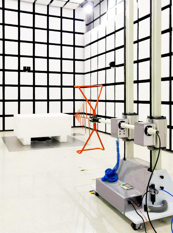
For a Standard 3m Method Anechoic Chamber, the receiving antenna must also be mounted correctly and positioned according to the required measurement procedure.
When using an automated GEAM-4600 Antenna Mast System, verify mounting compatibility, load limits, polarization movement, and cable clearance before starting automatic antenna-height scans.
How to Check Whether Antenna Performance Has Changed
A visual inspection cannot detect every change in antenna performance.
Laboratories can perform intermediate performance checks using established reference measurements.
For a receiving antenna, these may include:
– Comparing received levels from a repeatable RF source
– Checking measurement-chain consistency
– Monitoring unexpected changes at selected frequencies
– Reviewing previous antenna performance records
For transmitting antennas, return-loss or VSWR measurements can help identify problems in the RF path.
However, an acceptable VSWR measurement does not prove that antenna gain, radiation pattern, or receiving antenna factor remains unchanged.
Reference measurements are useful for detecting changes, but they do not replace formal calibration when calibration is required.
When Should an EMC Antenna Be Recalibrated?
Recalibration should be considered when the antenna’s electrical characteristics may have changed.
Important triggers include:
– Accidental dropping or significant impact
– Bent or replaced radiating elements
– RF connector damage or repair
– Changes to the feed structure
– Unexpected measurement differences
– Suspected water or corrosion damage
– Expiration of the assigned calibration interval
There is no universal recalibration interval for all EMC antennas.
The schedule should reflect manufacturer guidance, laboratory quality procedures, equipment history, and applicable accreditation requirements.
For guidance on interpreting the calibration results, see Understanding Antenna Calibration Certificates for EMC Testing.
Antenna Maintenance Decision Guide
When a problem is found, the action should depend on its potential effect on performance.
| Condition | Recommended Action |
|---|---|
| Light dust on approved external surfaces | Clean according to manufacturer instructions |
| Loose mounting hardware | Secure and verify correct mounting |
| Contaminated RF connector | Inspect and clean using approved procedures |
| Bent or broken antenna element | Remove from use and obtain technical assessment |
| Damaged RF connector | Arrange inspection or repair and assess recalibration |
| Unexpected change in RF response | Investigate the measurement chain and antenna |
| Active antenna power fault | Check power supply and manufacturer diagnostics |
| Suspected change in calibrated characteristics | Arrange appropriate verification or recalibration |
When damage affects the radiating elements, feed structure, or RF connector, the antenna should not be returned to compliance measurements until its suitability has been established.
EMC Antenna Maintenance and Storage Checklist
A simple inspection record helps laboratories manage antennas used across multiple test systems.
Before testing
– Confirm antenna model and serial number.
– Check physical condition and element alignment.
– Inspect RF connector and cable connections.
– Verify mounting stability.
– Confirm calibration status.
– Check active antenna power and indicators where applicable.
After testing
– Disconnect RF power before handling transmitting antennas.
– Allow components to cool where necessary.
– Inspect for damage.
– Clean approved external surfaces if required.
– Install connector protection caps.
– Return the antenna to its designated storage location.
During periodic maintenance
– Review mechanical fasteners and connection points.
– Check for corrosion or environmental damage.
– Compare reference measurements where applicable.
– Review calibration and repair records.
– Investigate unexplained performance changes.
A maintenance log should record the antenna identification, inspection date, observed condition, corrective action, and person responsible. These records help laboratories distinguish normal measurement variation from problems caused by mechanical damage, aging, or improper handling.