

In EMC emissions testing, the antenna and EMI receiver are only part of the measurement chain. The RF cable, connectors, adapters, and preamplifier between them can directly affect the measured signal and the final corrected field strength.
A typical radiated emissions receiving path is:
EMC Antenna → RF Cable → Preamplifier → EMI Receiver
The corrected field strength is generally calculated as:
Field Strength = Receiver Reading + Antenna Factor + Cable Loss − Preamplifier Gain
If any of these correction values are wrong, the final dBµV/m result will also be wrong.
This is why an EMC measurement system should be treated as one calibrated signal chain rather than as a collection of independent components.
RF Cable Loss Must Be Included in the Measurement
Every coaxial cable introduces insertion loss, and that loss normally increases with frequency.
If the antenna produces a 50 dBµV signal and the RF cable introduces 3 dB of loss, only about 47 dBµV reaches the next stage of the measurement chain.
The test software must therefore add the cable loss back into the final result.
For broadband EMC testing, a frequency-dependent cable-loss table should be used rather than one fixed correction value.
Cable selection should consider:
* Frequency range
* Total insertion loss
* Cable length
* Shielding effectiveness
* Mechanical flexibility
* Connector type
* Minimum bend radius
High-frequency measurements are particularly sensitive to cable condition because repeated bending, connector stress, or internal damage can change RF performance.
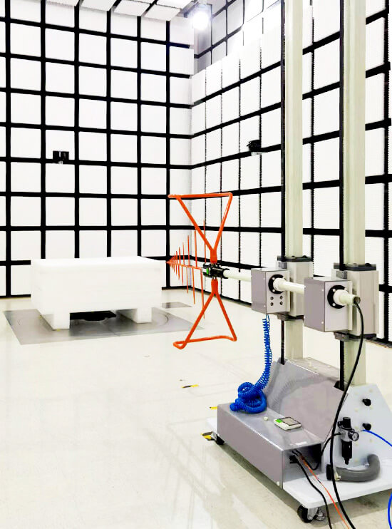
When the cable is installed on an automated antenna mast and turntable system, it should be supported so that height scanning and polarization changes do not pull the antenna out of alignment.
Connectors and Adapters Add More Than Simple Loss
Every connector creates a small discontinuity in the 50-ohm RF path.
A single good-quality connector normally introduces only a small effect, but an EMC test setup may contain several connection points:
* Antenna connector
* Cable connector
* Preamplifier input and output
* Chamber feedthrough
* RF adapter
* EMI receiver input
Multiple adapters increase both insertion loss and impedance mismatch.
At lower frequencies, these effects may be relatively small. At several gigahertz, connector quality and mechanical condition become much more important.
Unnecessary adapters should therefore be removed wherever possible.
For example, repeatedly converting between N-type, SMA, and precision microwave connectors increases both RF loss and the number of possible failure points.
Connector Problems Often Appear as Poor Repeatability
A damaged connector does not always create a complete signal failure.
More commonly, it produces unstable or frequency-dependent results.
Typical symptoms include:
* Measurement level changes when the cable is touched
* Sudden dips at specific frequencies
* Poor repeatability between scans
* Unexpected increases in system loss
* Different results after reconnecting the cable
* Receiver noise floor changing unexpectedly
Possible causes include:
* Worn threads
* Damaged center contacts
* Contamination
* Loose mating
* Incorrect torque
* Mechanical stress on the connector
Precision microwave connectors require particularly careful handling.
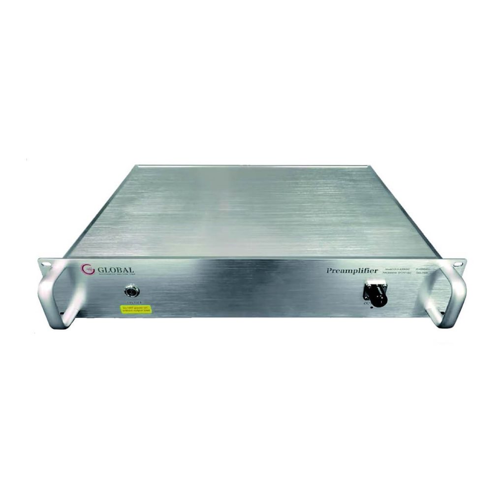
The GE RF Preamplifier 1313-A1840 uses 2.92 mm K connectors for high-frequency measurements. At these frequencies, connector condition becomes part of measurement accuracy rather than simply a mechanical issue.

Why Preamplifiers Are Used in EMC Testing
A preamplifier is used when the RF signal from the antenna is close to the measurement-system noise floor.
Its purpose is to amplify weak emissions before they reach the EMI receiver.
Preamplifiers are particularly useful for:
* Weak radiated emissions
* Measurements above 1 GHz
* Systems with long antenna cables
* Antennas with relatively high antenna factor
* Pre-compliance measurements
* Tests where emissions are close to the regulatory limit
The available RF preamplifier range includes broadband models covering different EMC and RF measurement bands.
For example, the 1313-A30M6G RF Preamplifier uses a 50-ohm matched input and output, allowing it to integrate into a standard EMC receiving chain.
Preamplifier Gain Must Be Corrected Accurately
The preamplifier increases the signal seen by the EMI receiver, so its gain must be subtracted when calculating the actual field strength.
For example:
* Receiver reading: 45 dBµV
* Antenna factor: 15 dB/m
* Cable loss: 3 dB
* Preamplifier gain: 30 dB
The corrected result is:
45 + 15 + 3 − 30 = 33 dBµV/m
If the software applies 27 dB of preamplifier gain instead of the actual 30 dB, the final result will be 3 dB too high.
This is why the gain curve of the actual preamplifier should be used.
A catalog statement such as 30 dB gain is not sufficient for accurate broadband measurements because amplifier gain normally changes with frequency.
Noise Figure Determines Whether the Preamplifier Actually Improves Sensitivity
High gain does not automatically mean better measurement sensitivity.
Noise figure is equally important.
A low-noise preamplifier increases weak signals while adding relatively little internal noise. This improves the overall system noise floor and helps the EMI receiver distinguish weak emissions from background noise.
The 1313-A1840 RF Preamplifier specifies a noise figure of up to 3.0 dB and a 50-ohm input/output impedance.
When selecting a preamplifier for EMC measurements, review:
* Frequency range
* Gain
* Gain flatness
* Noise figure
* Input VSWR
* Output VSWR
* Maximum input level
* Compression point
* Connector type
A preamplifier with very high gain but poor noise performance may offer less benefit than expected.
Too Much Preamplifier Gain Can Create Measurement Errors
A preamplifier improves weak-signal sensitivity only while it remains within its linear operating range.
Strong signals can drive the amplifier into compression.
This may be caused by:
* Strong EUT emissions
* Nearby radio transmitters
* Cellular signals
* Wi-Fi signals
* Broadcast stations
* Other laboratory equipment
Once the preamplifier enters compression, its output is no longer proportional to the input.
Possible symptoms include:
* Measured peaks lower than expected
* Unstable readings
* Unexpected harmonic products
* Intermodulation signals
* EMI receiver overload
* Significant differences with the preamplifier enabled and disabled
An overload problem may therefore look like an EMC failure or measurement inconsistency when the real problem is the receiving chain.
If overload is suspected, the laboratory can repeat the measurement without the preamplifier or introduce suitable filtering or attenuation.
Preamplifier Position Affects the System Noise Floor
For weak-signal measurements, the preamplifier is generally more effective when installed closer to the receiving antenna.
Compare:
Antenna → Long Cable → Preamplifier → Receiver
with:
Antenna → Preamplifier → Long Cable → Receiver
In the first arrangement, the weak antenna signal is attenuated before amplification.
In the second arrangement, the signal is amplified before passing through the cable, so the cable has less influence on the overall system sensitivity.
This becomes especially useful at microwave frequencies.
However, placing a preamplifier near the antenna also requires attention to:
* Power supply arrangement
* Chamber background emissions
* Mechanical mounting
* Maximum input level
* RF cable movement
* Shielding
The best location should balance sensitivity improvement with chamber cleanliness and mechanical practicality.
Input VSWR and Impedance Matching Also Matter
Most EMC receiving systems are designed around a 50-ohm impedance.
The antenna, RF cable, preamplifier, adapters, and EMI receiver should therefore maintain a reasonably consistent 50-ohm signal path.
Poor impedance matching creates reflections between components.
These reflections can produce:
* Frequency-dependent amplitude changes
* Standing-wave effects
* Reduced signal transfer
* Increased measurement uncertainty
This becomes more important as frequency increases and cable electrical length becomes larger.
Checking only insertion loss is therefore not enough. The VSWR or return loss of critical RF components should also be considered.
Correction Files Must Match the Actual Setup
One of the most common practical EMC measurement mistakes is using correction data that does not match the installed hardware.
The software correction file should correspond to:
* The exact antenna
* The actual RF cable
* The installed preamplifier
* Any relevant adapters
* The current configuration
Correction data should be reviewed whenever:
* A cable is replaced
* A connector is repaired
* An adapter is added or removed
* A different preamplifier is installed
* The preamplifier is bypassed
* The measurement frequency range changes
A measurement system can be mechanically connected correctly while still producing incorrect results because the wrong correction file is active.
The article Key Factors Affecting EMC Antenna Measurement Accuracy explains how antenna calibration, positioning, chamber performance, receiver settings, and correction data combine in the complete measurement uncertainty.
Watch the Complete System Noise Floor
Before testing the EUT, the laboratory should perform a background scan with the same antenna, cable, preamplifier, and EMI receiver configuration.
This establishes the actual noise floor of the complete measurement system.
If the expected EUT emission is only slightly above the noise floor, the measurement may have poor sensitivity even when the receiver itself has excellent specifications.
The system noise floor can be affected by:
* Antenna sensitivity
* Preamplifier noise figure
* Preamplifier gain
* Receiver internal noise
* RF cable loss
* Ambient RF signals
* Chamber background emissions
A preamplifier should improve the usable system noise floor without causing overload from stronger signals elsewhere in the spectrum.
Practical Measurement Chain Checklist
Before starting a radiated emissions measurement, confirm:
* The correct RF cable-loss file is loaded.
* Cable condition is stable and undamaged.
* Connectors are clean and secure.
* Unnecessary adapters have been removed.
* The signal path maintains 50-ohm impedance.
* The correct preamplifier gain file is selected.
* Preamplifier noise figure is suitable for the measurement.
* Maximum input level will not be exceeded.
* The preamplifier is not operating in compression.
* The EMI receiver is not overloaded.
* The complete system noise floor has been checked.
* Antenna-factor data matches the actual antenna.
Unexpected EMC measurement changes should not automatically be attributed to the EUT. A loose connector, wrong preamplifier correction, amplifier overload, or mismatch in the RF receiving path can produce equally significant changes in the recorded result.










