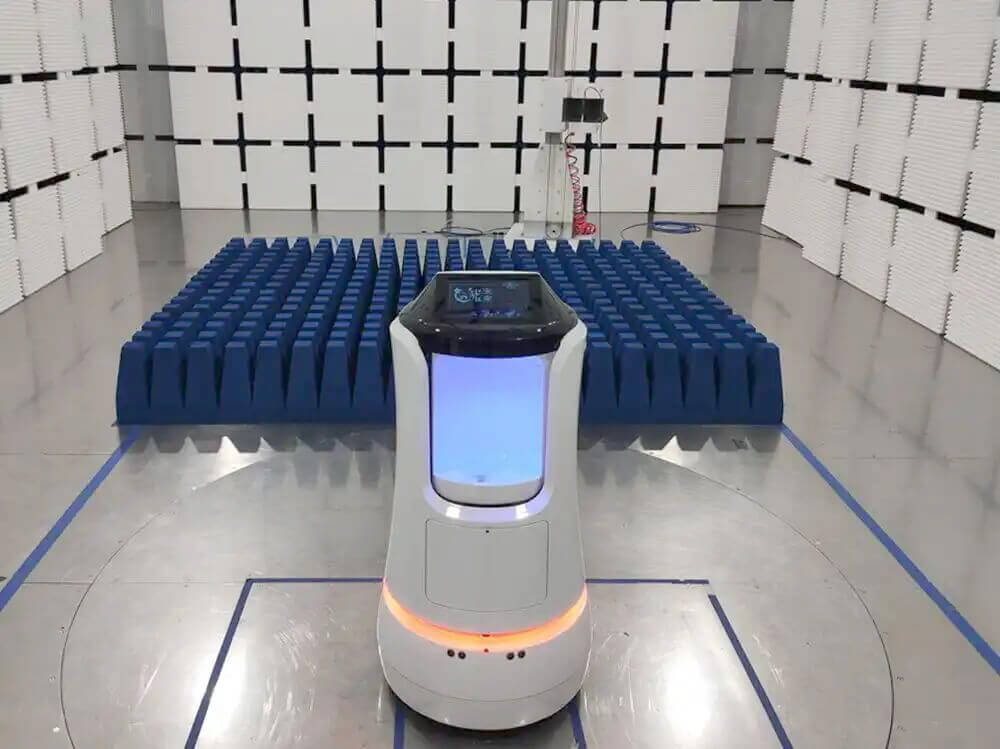
Radiated EMC testing may require measurements from tens of megahertz to several gigahertz. A traditional setup often uses several antennas to cover this range, such as a biconical antenna for lower frequencies, a log-periodic antenna for VHF and UHF measurements, and a horn antenna for microwave frequencies.
Every antenna change interrupts the test. The operator may need to enter the chamber, lower the antenna mast, disconnect the RF cable, replace the antenna, adjust the mount, verify polarization, select another calibration file, and restart the test sequence.
Broadband EMC antennas reduce these interruptions by covering a wider frequency range with one antenna. Their value is not limited to bandwidth. They also improve automated test continuity, reduce setup variation, and simplify calibration management.
Fewer Antenna Changes
Changing an EMC antenna involves more than replacing one physical device.
The operator normally needs to:
* Pause the test software
* Open the chamber
* Move the antenna mast
* Disconnect and reconnect RF cables
* Install the correct antenna adapter
* Confirm antenna height and direction
* Check horizontal or vertical polarization
* Select the correct calibration file
* Restart the scan
This process adds test time and creates opportunities for setup errors.
A broadband antenna can cover several adjacent test bands without manual intervention. This is particularly useful in commercial EMC laboratories, production test facilities, and engineering laboratories that test several products each day.
Faster Automated Radiated Emissions Testing
An automated radiated emissions test may search:
* Frequency
* EUT rotation angle
* Antenna height
* Antenna polarization
* EUT operating mode
If the antenna must be replaced several times, the automated sequence stops at each transition frequency.
A broadband antenna allows the EMI receiver to continue scanning across a larger frequency range while the automated positioning system controls the turntable, antenna mast, height scan, and polarization.
A typical automated pre-scan can:
1. Load the broadband antenna calibration data.
2. Set vertical polarization.
3. Rotate the EUT through 360 degrees.
4. Record the maximum emissions.
5. Scan antenna height at selected frequencies.
6. Switch to horizontal polarization.
7. Repeat the search.
8. Return to the maximum positions for final measurements.
Reducing manual interruptions makes the test faster and improves repeatability.
Fewer Frequency Transition Errors
When several antennas divide the test range, their frequency bands normally overlap.
For example, one antenna may cover 30 MHz to 300 MHz, while another covers 200 MHz to 1 GHz. The laboratory must decide where to switch between them.
A poor transition point may result in:
* Higher antenna factor
* Lower receiving sensitivity
* Poorer VSWR
* Lower antenna gain
* Unstable radiation pattern
* Missing correction data
There is also a risk that the software uses the wrong antenna file or creates a small gap between the two measurement ranges.
A broadband antenna reduces the number of transition points and creates a more continuous radiated emissions scan.
Hybrid Antennas for Wide Frequency Coverage
Hybrid antennas combine lower-frequency dipole or biconical elements with a log-periodic structure.
This design extends frequency coverage toward the lower VHF range while retaining directional broadband performance at higher frequencies.
The 1313-3-30M6G hybrid antenna covers 30 MHz to 6 GHz and can be used for receiving and transmitting applications.
Using one antenna across this range can reduce the need to switch between separate biconical, log-periodic, and lower-frequency horn antennas.
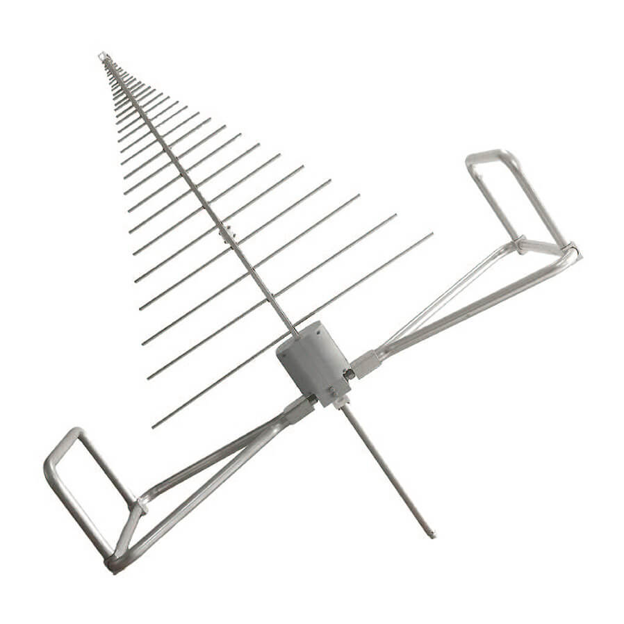
This type of broadband EMC antenna is suitable for:
* Radiated emissions pre-scanning
* EMC pre-compliance testing
* Broadband RF monitoring
* EMC troubleshooting
* Automated test systems
* Moderate-field radiated immunity testing
The wide frequency range does not guarantee equal performance at every frequency. Antenna factor, gain, VSWR, beamwidth, and power handling must still be reviewed across the complete band.
Broadband Log-Periodic Antennas
Log-periodic antennas are widely used in EMC testing because they provide broadband operation, directional radiation, and linear polarization.
The OVLP-00330 high-performance log-periodic antenna covers 30 MHz to 3 GHz and is supplied with detailed calibration data across the operating range.
This allows the test software to apply frequency-dependent antenna-factor corrections without changing antennas during the scan.
A wideband log-periodic antenna is useful for measuring emissions from:
* Digital electronics
* Industrial control equipment
* Medical devices
* Automotive electronics
* Wireless products
* Power converters
* Communication equipment
Where the lower-frequency range is already covered by a dedicated biconical antenna, the OLP-230 log-periodic antenna can provide coverage from 200 MHz to 3 GHz.
This arrangement may provide better low-frequency sensitivity while still reducing the total number of antenna changes.
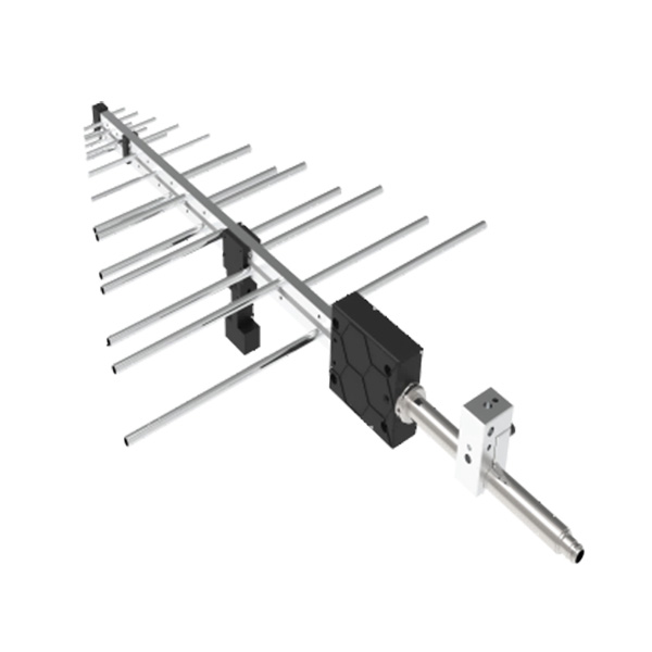
Broadband Horn Antennas Above 1 GHz
Above 1 GHz, a broadband dual-ridged horn antenna can cover several microwave bands with one antenna.
The OBH-08180 broadband dual-ridged horn antenna operates from 0.8 GHz to 18 GHz.
It can support:
* High-frequency radiated emissions
* Radiated immunity testing
* Wireless device evaluation
* Radar and microwave measurements
* Automotive electronic testing
* Satellite communication equipment
* Aerospace and defense applications
Using one horn antenna across a broad microwave range reduces the need to install separate antennas for several narrower waveguide bands.
More information about horn antenna selection is available in Applications of Dual-Ridged Horn Antennas in EMC Testing.
Improved Test Repeatability
Every antenna change can introduce small differences into the setup.
Common sources of variation include:
* Different connector torque
* Changed RF cable position
* Incorrect antenna height
* Small boresight changes
* Wrong polarization
* Incorrect antenna adapter
* Different cable bending radius
* Wrong correction file
These differences may affect measured amplitude, particularly at higher frequencies.
Using one broadband antenna over a larger range reduces the number of times the setup is disturbed. This improves consistency between pre-scan, final measurement, troubleshooting, and repeated tests.
Simpler Calibration Management
Each receiving antenna requires its own antenna-factor file. Immunity systems may also require gain, VSWR, forward-power, and field-calibration data.
A laboratory using many antennas must manage:
* Multiple serial numbers
* Different calibration dates
* Several antenna-factor files
* Different frequency intervals
* Overlapping antenna ranges
* Separate cable-loss data
* Antenna transition settings
A broadband antenna reduces the number of correction files required for one complete scan.
However, the calibration data still needs sufficient frequency resolution. A wideband antenna covering several gigahertz should not be represented by only a few widely spaced correction points.
The software must associate each calibration file with the correct antenna serial number and cable path.
Broadband Antennas in Radiated Immunity Testing
Broadband antennas can also reduce setup changes during radiated immunity testing.
A traditional immunity system may use different antennas and amplifier paths for:
* 80 MHz to 1 GHz
* 1 GHz to 6 GHz
* 6 GHz to 18 GHz
A broadband antenna may cover more than one of these ranges, but the complete RF chain must support the same frequencies.
The system may still require several:
* RF power amplifiers
* Directional couplers
* RF switches
* Coaxial cables
* Connectors
* Field probes
Broadband antennas reduce antenna changes, but they do not automatically eliminate amplifier switching.
The antenna must also provide sufficient power handling and suitable field uniformity across the complete test range.
Test Efficiency and Technical Performance
The widest antenna is not always the best antenna.
A broadband model may have:
* Higher antenna factor at lower frequencies
* Lower gain in part of the range
* Greater radiation-pattern variation
* Lower power handling than a specialized antenna
* Larger physical dimensions
* Wider VSWR variation
A dedicated antenna may provide better sensitivity or stronger field generation within a narrower band.
For example:
* A biconical antenna may provide better low-frequency emissions sensitivity.
* A high-power log-periodic antenna may be more suitable for 80 MHz to 1 GHz immunity testing.
* A high-gain horn may require less amplifier power at microwave frequencies.
* A smaller antenna may fit more easily inside a compact chamber.
The antenna configuration should balance test speed, measurement uncertainty, receiving sensitivity, field strength, and chamber space.
Example Coverage from 30 MHz to 18 GHz
A practical broadband EMC antenna arrangement could include:
30 MHz to 3 GHz or 6 GHz
Use a hybrid or wideband log-periodic antenna:
* OVLP-00330: 30 MHz to 3 GHz
* 1313-3-30M6G: 30 MHz to 6 GHz
0.8 GHz to 18 GHz
Use a broadband dual-ridged horn antenna:
* OBH-08180: 0.8 GHz to 18 GHz
The overlap between the antennas allows the laboratory to compare:
* Antenna factor
* Gain
* VSWR
* Beamwidth
* Measurement uncertainty
* Power handling
* Field uniformity
The transition frequency should be selected from calibration and system-performance data rather than only from the published frequency limits.
Selecting a Broadband EMC Antenna
Before selecting a broadband antenna, confirm:
* Required frequency range
* Radiated emissions, immunity, or both
* Antenna factor across the band
* Gain versus frequency
* Typical and maximum VSWR
* RF power handling
* Beamwidth
* Calibration frequency interval
* Connector type
* RF cable loss
* Antenna dimensions and weight
* Antenna mast compatibility
* Chamber clearance
* Field-uniformity requirements
* Test software compatibility
Broadband antennas are most effective when they are treated as part of the complete EMC measurement system], rather than selected only from the widest available frequency range.