

In radiated EMC testing, the highest emission level is rarely found by placing the equipment under test in one fixed position and taking a single measurement.
The result can change as the equipment rotates, the receiving antenna moves vertically, and the antenna polarization switches between horizontal and vertical. Enclosure seams, ventilation openings, displays, connectors, external cables, printed circuit boards, and internal wiring may all radiate differently depending on their orientation relative to the measurement antenna.
This is why an automated EMC testing system normally includes an EMC turntable, antenna mast, positioning controller, test software, and an anechoic or semi-anechoic chamber.
A properly integrated anechoic chamber positioning system does more than move equipment. It controls EUT angle, antenna height, polarization, scanning speed, and measurement sequence, helping the test system identify the maximum radiated emission in a repeatable way.
Why Positioning Changes Radiated EMC Test Results
Electronic equipment does not radiate electromagnetic energy equally in every direction.
A switching power supply may produce stronger emissions near the AC or DC power input. A display interface may radiate through a cable connector. A metal enclosure may allow RF energy to escape through ventilation openings or panel joints. An industrial controller with several external cables may show different emission levels as each cable is turned toward the receiving antenna.
The measured field strength can therefore change with:
* EUT rotation angle
* Antenna height
* Antenna polarization
* Antenna-to-EUT distance
* Cable arrangement
* EUT operating mode
* Position of auxiliary equipment
* Antenna boresight angle
During radiated emissions testing, the objective is to identify the combination of EUT angle, antenna height, and antenna polarization that produces the maximum measured disturbance at each significant frequency.
Manual positioning may be acceptable for basic EMC pre-compliance testing. It becomes inefficient when the test covers hundreds or thousands of frequency points, two antenna polarizations, multiple antenna types, and a complete 360-degree rotation of the EUT.
Automated turntables and antenna masts allow the EMC test software to repeat the same positioning sequence with controlled mechanical accuracy.
What an EMC Turntable Does
An EMC turntable rotates the equipment under test inside the chamber while keeping it within the calibrated test area or quiet zone.
It allows the measurement system to evaluate radiated emissions from different sides of the EUT without requiring an operator to enter the chamber and reposition the equipment manually.
During an automated radiated emissions test, the turntable may operate using continuous rotation, step-by-step positioning, or a combination of both.

Continuous Turntable Rotation
During continuous rotation, the turntable moves while the EMI receiver or spectrum analyzer monitors selected frequencies.
This method is useful during a fast radiated emissions pre-scan. The EMC software can record the highest amplitude observed during a complete rotation and identify the approximate EUT angle at which the maximum occurred.
Continuous rotation reduces test time, but turntable speed must be coordinated with:
* Receiver sweep time
* Detector response
* Measurement bandwidth
* Dwell time
* Data acquisition rate
* Frequency step size
If the turntable rotates too quickly, a narrow angular maximum may pass before the receiver completes its measurement.
Step-by-Step Turntable Rotation
During step rotation, the turntable moves to a defined angle, stops, and allows the receiver to take a measurement before moving to the next position.
The angle increment depends on the EUT size, radiation characteristics, applicable EMC standard, and required measurement resolution.
Smaller angle increments provide more detailed angular information but increase total test time.
Step-by-step rotation is commonly used when:
* The EUT has a directional emission source
* Final measurements are being performed
* The receiver requires a longer dwell time
* A repeatable fixed angle is required
* The laboratory is investigating a specific failure frequency
* A design change must be compared at the same EUT orientation
Many automated EMC test procedures use continuous rotation for the initial pre-scan and step positioning for final emission maximization.
Finding the Maximum Radiated Emission Angle
The strongest radiated emission does not always occur when the front or rear of the product faces the measurement antenna.
The maximum level may occur at an intermediate angle because an external cable, printed circuit board trace, enclosure seam, connector, or internal wiring harness forms an effective radiating structure at that orientation.
An automated EMC turntable can search the full 0-to-360-degree range while the EMI receiver monitors selected frequencies. Once the test software identifies a likely maximum, the turntable can return to that position for a more accurate peak, quasi-peak, average, or RMS measurement.
This process is particularly useful when testing:
* Automotive electronic modules
* Industrial control equipment
* Information technology equipment
* Medical electrical equipment
* Wireless devices
* Power converters and inverters
* Battery management systems
* Large equipment with external cables
* UAV and drone electronic systems
For large or irregularly shaped equipment, turntable diameter and load capacity must be selected according to the complete test setup rather than the EUT alone.
Fixtures, support tables, cable harnesses, artificial networks, loads, batteries, and auxiliary equipment may also need to be placed on or around the rotating platform.
Turntable Diameter and Load Capacity
A turntable that is too small may place part of the EUT or its cable arrangement outside the calibrated test area.
A platform with insufficient load capacity may suffer from mechanical deformation, unstable movement, reduced positioning accuracy, or premature drive-system wear.
Important EMC turntable specifications include:
* Platform diameter
* Maximum load capacity
* Rotation range
* Rotation speed
* Angular positioning accuracy
* Platform height
* Flush-mounted or above-floor installation
* Cable routing provisions
* Mechanical stability
* Electromagnetic emissions from the drive system
* Remote-control interface
The GETT-2000 turntable system uses a two-meter rotating platform and supports a maximum load of 1.5 tons. It provides a configurable rotation range of up to 360 degrees, an adjustable speed from 0.5 to 2 rpm, and positioning accuracy of ±1 degree.
Its flush-mounted structure keeps the rotating platform level with the chamber floor. This makes it easier to move heavy test equipment onto the platform and reduces the need for raised ramps or temporary support structures.
A flush-mounted EMC turntable is particularly useful for:
* Floor-standing industrial equipment
* Electrical cabinets
* Automotive assemblies
* Test racks
* Large power converters
* Battery systems
* Equipment moved on wheels or handling tools
Why Turntable Positioning Accuracy Matters
Turntable positioning accuracy affects whether the laboratory can return to the same EUT orientation during troubleshooting, final testing, and repeated measurements.
Suppose an emission peak is identified at approximately 126 degrees. The engineer may need to return to that position after changing a cable, adding a ferrite core, modifying shielding, replacing a printed circuit board, or changing the grounding arrangement.
If the turntable cannot reproduce the same angle accurately, it becomes difficult to determine whether a change in measured emission level resulted from the product modification or from a different EUT orientation.
Turntable positioning repeatability is important for:
* EMC failure investigation
* Design-change verification
* Before-and-after comparisons
* Final compliance measurements
* Laboratory correlation
* Repeated production testing
* Validation of corrective actions
Mechanical backlash, platform movement under load, incorrect zero-angle calibration, and poor load centering can reduce practical positioning accuracy even when the controller displays the requested angle.
What an Antenna Mast Does
An EMC antenna mast moves the measurement antenna vertically and switches it between horizontal and vertical polarization.
In many radiated emissions test configurations, particularly below 1 GHz, the receiving antenna is scanned through a defined height range to locate the maximum signal.
The exact antenna height scan depends on:
* Applicable EMC standard
* Test distance
* Chamber design
* EUT dimensions
* Measurement frequency
* Ground-plane configuration
* Antenna type
* Laboratory test procedure
Changing antenna height changes the direct and reflected signal paths between the EUT and the receiving antenna. These signals can combine constructively or destructively, producing signal maxima and minima at different antenna heights.
A measurement taken at only one antenna height may therefore be lower than the actual maximum radiated disturbance.
The antenna mast allows the automated EMC test system to search this vertical field distribution in a controlled and repeatable manner.
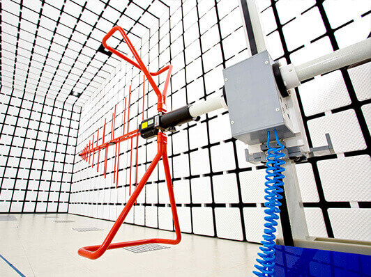
Antenna Height Scanning in Radiated Emissions Testing
A typical automated antenna height scan follows several stages:
1. The turntable moves to a selected EUT angle.
2. The antenna is set to horizontal or vertical polarization.
3. The antenna mast moves through the programmed height range.
4. The EMI receiver monitors the selected emission frequency.
5. The software records the antenna height that produces the highest level.
6. The process is repeated using the other antenna polarization.
7. The system returns to the maximum angle, height, and polarization for final measurement.
This coordinated search is more reliable than manually adjusting antenna height while watching a receiver display.
Antenna height scanning is especially important at lower frequencies, where reflections from the conductive ground plane and chamber surfaces can strongly influence the received signal.
At higher frequencies, the applicable test procedure may use different height, boresight, or measurement-volume requirements. The antenna mast sequence should therefore follow the relevant product standard rather than applying the same height scan to every frequency range.
Horizontal and Vertical Antenna Polarization
Most radiated emissions test procedures require measurements in both horizontal and vertical antenna polarization.
The polarization that produces the highest reading depends on the orientation of the radiating source.
A vertical cable may couple more strongly to a vertically polarized antenna. A horizontal enclosure slot, printed circuit board structure, or cable arrangement may produce a stronger response when the antenna is horizontally polarized.
Automatic polarization switching allows the EMC test software to evaluate both orientations without requiring an operator to enter the chamber and manually rotate the antenna.
This provides several practical advantages:
* Shorter test time
* Consistent antenna orientation
* Fewer interruptions during automated testing
* Reduced risk of selecting the wrong polarization
* Better measurement repeatability
* Easier unattended emissions pre-scanning
The GEAM-4600 antenna mast system supports pneumatic switching between 0-degree and 90-degree antenna polarization.
Pneumatic switching can reduce the need to place an additional electrical motor close to the EMC measurement antenna, helping to limit unwanted electromagnetic noise inside the chamber.
Antenna Mast Height, Load Capacity, and Tilt
An antenna mast must support more than vertical movement.
Its mechanical design has to accommodate different antenna sizes, weights, mounting adapters, RF cables, and polarization mechanisms.
A compact biconical antenna places different mechanical demands on the mast than a large high-power log-periodic antenna or broadband dual-ridged horn antenna.
Important antenna mast specifications include:
* Total mast height
* Usable antenna centerline range
* Maximum antenna load
* Height scan speed
* Height positioning accuracy
* Polarization switching method
* Antenna tilt range
* Structural material
* RF cable management
* Limit switches
* Safety protection
* Controller compatibility
* EMC test software compatibility
The GEAM-4600 provides antenna centerline movement from 1,000 to 4,000 mm, with a maximum load of 10 kg.
Its adjustable height scan speed ranges from 1 to 8 cm/s, while the listed positioning accuracy is ±1 cm.
The antenna mast also provides a tilt range of approximately -0.3 to 45 degrees. Antenna tilt is useful when the antenna must remain directed toward the EUT during vertical movement, especially in larger chambers or when testing tall equipment.
Why Antenna Boresight Matters
An EMC antenna does not have equal sensitivity or gain in every direction.
Directional antennas, including log-periodic antennas and broadband dual-ridged horn antennas, are designed to point toward the equipment under test.
When the antenna moves vertically, its physical position changes while the EUT remains fixed. In some test configurations, the antenna may need to tilt so that its boresight continues to point toward the center of the EUT or the defined measurement volume.
Without suitable antenna tilt, the EUT may move away from the antenna’s main beam at the upper or lower ends of the height scan. This can affect measurement sensitivity during radiated emissions testing and field generation during radiated immunity testing.
Antenna boresight becomes more important when:
* The measurement distance is short
* The antenna height range is large
* A directional high-gain antenna is used
* The EUT is tall
* The chamber supports large equipment
* Radiated immunity field uniformity is being evaluated
The mast structure and antenna adapter must maintain alignment during elevation, tilt, and polarization changes.
Coordinating Turntable and Antenna Mast Movement
The main benefit of an automated EMC positioning system comes from coordinated movement.
A turntable or antenna mast operating alone can reduce manual work. Full EMC test automation requires the positioning devices to exchange commands and status information with the controller, EMI receiver, and test software.
A typical automated radiated emissions sequence may include:
* Selecting the antenna and test frequency range
* Moving the antenna to its starting height
* Selecting vertical polarization
* Rotating the EUT through 360 degrees
* Recording the maximum emission angles
* Scanning antenna height at selected angles
* Repeating the sequence in horizontal polarization
* Returning to the maximum angle and antenna height
* Performing final detector measurements
* Saving frequency, amplitude, angle, height, and polarization data
* Generating the EMC test report
The positioning system must confirm that each movement is complete before the EMI receiver begins the next measurement.
If the software records data before the turntable stops or while the antenna mast is still moving, the recorded position may not match the actual measurement position.
The Role of the EMC Positioning Controller
The positioning controller connects the mechanical turntable and antenna mast to the automated EMC test software.
It receives movement commands, controls motors and pneumatic devices, monitors position feedback, and reports the current equipment status to the computer.
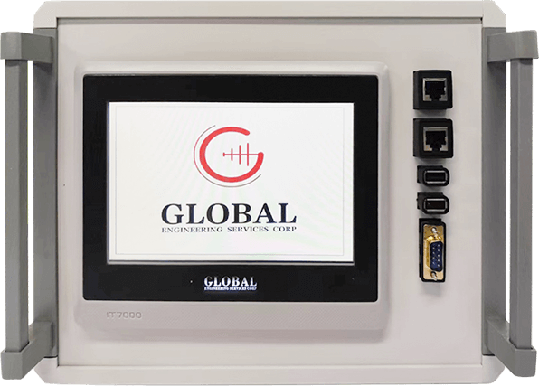
The GEC-3 positioning controller integrates PLC control, touchscreen operation, fiber-optic communication, and LAN connectivity.
It supports TCP/IP communication through RJ45 interfaces and also provides USB, RS232, and SC optical-fiber connections.
The controller allows the positioning system to operate in several modes:
* Local touchscreen control
* Manual positioning
* Independent turntable control
* Independent antenna mast control
* Coordinated turntable and antenna mast operation
* Remote control through EMC test software
Manual operation remains important even in a fully automated EMC laboratory. Operators still need to move the turntable and antenna mast during EUT setup, antenna replacement, maintenance, chamber validation, and troubleshooting.
Why Fiber-Optic Control Is Used Inside EMC Chambers
Control cables and electronic devices inside an anechoic chamber can become unwanted sources of electromagnetic noise.
Copper communication cables may conduct or radiate interference. They may also affect the electromagnetic environment if they are not properly filtered, shielded, and routed.
Fiber-optic communication provides electrical isolation between the controller and the positioning equipment.
Because optical fiber does not carry electrical current, it reduces the possibility of the control system introducing conducted or radiated interference into the EMC measurement environment.
The GETT-2000 turntable and GEAM-4600 antenna mast use polymer optical-fiber communication. Their electrical drive components are designed to keep generated interference below the required chamber background-noise level.
Low-emission positioning equipment is important because noise from a turntable motor, antenna mast drive, controller, or switching power supply could otherwise be mistaken for an emission from the EUT.
Automated Pre-Scan and Final Measurement
Automated EMC testing does not normally measure every frequency using the slowest detector at every possible EUT angle and antenna height.
That approach would require excessive test time.
Most automated radiated emissions procedures divide the test into a fast pre-scan, emission maximization, and final measurement.
Pre-Scan Stage
The system performs a relatively fast frequency scan, normally using a peak detector.
The turntable and antenna mast search for likely maximum positions while the software creates a list of frequencies that:
* Exceed the applicable emissions limit
* Approach the limit within a selected margin
* Represent the highest emissions in each frequency range
* Require additional investigation
Emission Maximization Stage
For each selected frequency, the system searches the EUT angle, antenna height, and antenna polarization more carefully.
The turntable may rotate around the approximate maximum using smaller angle increments. The antenna mast may then move above and below the initial maximum height to refine the position.
Final Measurement Stage
Once the maximum position has been identified, the EMI receiver performs the required final measurement using the applicable detector and measurement bandwidth.
The software records:
* Emission frequency
* Measured amplitude
* Applicable limit
* Margin to the limit
* Turntable angle
* Antenna height
* Antenna polarization
* Antenna type
* Cable-loss correction
* Antenna-factor correction
This positioning information is essential when a failed emission must be reproduced during EMC troubleshooting.
Turntables and Antenna Masts in Radiated Immunity Testing
Positioning equipment is also used in radiated immunity testing, although its purpose is different.
Radiated emissions testing searches for the maximum RF energy produced by the EUT. Radiated immunity testing exposes the EUT to a controlled electromagnetic field and checks whether it continues to operate correctly.
The antenna mast may be used to set the transmitting antenna at the required height, polarization, and boresight angle.
The turntable may rotate the EUT so that different sides are exposed to the electromagnetic field.
For small products, the EUT may be tested in several defined orientations. Large equipment may require separate exposure of different surfaces because the complete product cannot always be covered uniformly from one transmitting antenna position.
The positioning arrangement must be coordinated with:
* Field-uniformity calibration
* EUT dimensions
* Antenna beamwidth
* Antenna gain
* Test distance
* Required field strength
* Cable routing
* EUT monitoring equipment
* Applicable radiated immunity standard
Antenna and turntable positions used during field calibration should be controlled carefully. Changing the transmitting antenna position after calibration can change the field distribution within the test area.
Positioning Systems for 3 m, 5 m, and 10 m Chambers
The required turntable and antenna mast depend heavily on the chamber size and intended EUT dimensions.
A compact 3 m chamber may be used for:
* Consumer electronics
* Wireless products
* Small industrial devices
* Medical equipment
* Automotive components
Larger 5 m and 10 m chambers may need to support:
* Complete vehicles
* Industrial cabinets
* Large machines
* UAV and drone systems
* Power conversion systems
* Equipment with extensive cable arrangements
The article Guidance on Selecting 3M, 5M, and 10M Anechoic Chambers for EMC Testing Applications explains how EUT dimensions, quiet-zone size, test distance, facility height, and structural load affect EMC chamber selection.
As chamber size increases, positioning requirements also become more demanding:
* Larger turntable diameter
* Higher load capacity
* Greater antenna mast height
* Longer antenna travel
* Higher structural stability
* More accurate antenna alignment
* Longer RF and control cable runs
* More complex safety interlocks
The turntable and antenna mast should be selected together with the chamber geometry rather than added after the shielded enclosure and absorber layout have already been finalized.
Common Positioning Errors in Automated EMC Testing
Automation reduces operator variability, but it does not eliminate setup errors.
Incorrect Turntable Zero Position
If the physical zero angle does not match the software reference, recorded EUT positions will be incorrect.
The laboratory may then be unable to reproduce the maximum emission angle during a later test.
EUT Positioned Away from the Rotation Center
An off-center EUT changes its distance from the antenna as the turntable rotates. It may also move outside the validated quiet zone.
The complete EUT, including its cables and fixtures, should remain within the intended test volume throughout rotation.
Poor Cable Arrangement
Power, signal, and communication cables may move, tighten, or change shape as the turntable rotates.
This can change their radiation characteristics and may also create a mechanical or electrical safety risk.
Cable routing must allow full turntable movement without dragging, twisting, or pulling connectors.
Excessive Turntable Speed
If turntable speed is not matched to EMI receiver dwell time and sweep speed, the system may miss a narrow angular maximum.
Antenna Cable Pulling on the Mast
Heavy or poorly supported RF cables can affect antenna height, polarization, and boresight alignment.
Cable movement can also change insertion loss or damage RF connectors.
Incorrect Antenna Height Reference
The mast display may indicate carriage position rather than the actual antenna centerline.
Antenna adapters, mounting brackets, and polarization mechanisms must be included when establishing the antenna height reference.
Insufficient Mast Load Capacity
The total mast load includes more than the antenna.
It may also include:
* Mounting bracket
* Polarization mechanism
* Antenna adapter
* Cable-support hardware
* Part of the RF cable weight
Motor or Controller Emissions
Electrical positioning equipment can create chamber background noise. This is especially serious during low-level radiated emissions measurements.
Movement Before Measurement Completion
The software must wait for the receiver measurement to finish before moving to the next angle or antenna height.
Incorrect command timing can associate a measured value with the wrong physical position.
Selecting an EMC Turntable and Antenna Mast System
Before specifying an automated EMC positioning system, the laboratory should define the complete testing requirement.
Turntable Requirements
* Maximum EUT dimensions
* Total EUT and fixture weight
* Required platform diameter
* Rotation range
* Rotation speed
* Angular positioning accuracy
* Flush-mounted or raised installation
* Cable routing method
* Floor loading
* Chamber quiet-zone dimensions
Antenna Mast Requirements
* Minimum and maximum antenna height
* Required height scan range
* Maximum antenna and adapter weight
* Height scan speed
* Height positioning accuracy
* Horizontal and vertical polarization switching
* Boresight tilt range
* Antenna mounting interfaces
* RF cable support
* Compatibility with different EMC antennas
Control and Automation Requirements
* Fiber-optic communication
* TCP/IP or serial control
* EMC software compatibility
* Position feedback
* Manual control mode
* Programmable movement sequences
* Emergency stop
* Mechanical limit protection
* Software limit protection
* Remote diagnostics
* Calibration and maintenance access
The positioning equipment should also be evaluated as part of the complete EMC measurement system, which includes the chamber, EMI receiver, measurement antennas, RF cables, RF amplifiers, field probes, control software, and related test accessories.
For laboratories planning a complete chamber, the Fully Anechoic Chamber page provides additional information on turntable capacity, automatic antenna polarization, adjustable antenna towers, quiet-zone requirements, and chamber dimensions.
Positioning System Verification and Maintenance
EMC turntables and antenna masts require regular inspection even when their movement appears normal.
A practical maintenance and verification program should include:
* Checking the turntable zero position
* Verifying angular positioning accuracy
* Confirming antenna height accuracy
* Testing horizontal and vertical polarization switching
* Inspecting mechanical limit switches
* Checking emergency-stop operation
* Inspecting fiber-optic communication
* Examining RF cable supports
* Checking rotating cable paths
* Confirming platform stability under load
* Listening for abnormal drive noise
* Measuring chamber background emissions while the system operates
* Confirming software position feedback
Position verification should also be performed after mechanical maintenance, controller replacement, software updates, antenna mast cable replacement, or any change that could affect movement accuracy.
The value of EMC test automation depends on the turntable, antenna mast, positioning controller, EMI receiver, and control software operating as one coordinated measurement system. Accurate mechanical positioning makes the search for maximum radiated emissions systematic, repeatable, and traceable.










