An EMC chamber can be installed in an existing building, provided the structure can accommodate the required test volume, equipment loads, RF shielding, electrical services, ventilation, and safety systems.
The main challenge is fitting a complete EMC testing environment into a building that was not originally designed for one. Ceiling beams, floor load limits, narrow access routes, existing utilities, and fire protection requirements can all affect the chamber layout.
Before selecting a chamber, engineers should evaluate both the EMC testing requirements and the building’s physical limitations. A site survey can identify whether a standard chamber configuration is suitable or whether building modifications or a customized design are required.
Define the EMC Testing Requirements First
The intended testing application determines the chamber configuration.
Before reviewing building dimensions, establish:
– Equipment Under Test (EUT) dimensions and weight
– Radiated emissions and immunity requirements
– Applicable CISPR, IEC, ANSI, or other standards
– Required test distance and frequency range
– EUT cable arrangements and supporting equipment
– Antenna movement and quiet-zone requirements
– Potential future expansion
A Standard 3m Method Anechoic Chamber is commonly considered for small and medium-sized electronic equipment.
Larger industrial products may require a 5m Method Anechoic Chamber or a larger test configuration.
A shorter test distance should not be selected solely because the building has limited space. The chamber must support the intended measurement procedure and validation requirements.
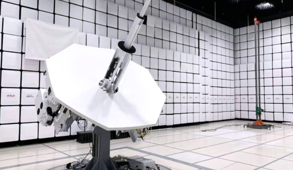
Check Available Space and Ceiling Height
A nominal 3 m test distance does not mean the chamber requires only 3 m of building length.
The enclosure must accommodate the EUT, receiving antenna, positioning equipment, RF absorbers, and required measurement geometry.
For example, the GE standard 3 m semi-anechoic chamber lists approximate internal dimensions of:
– Length: 9 m
– Width: 6 m
– Height: 6 m
These are reference dimensions, not a universal installation requirement.
The building must also provide space for the shielding structure, external services, installation work, and maintenance access.
Measure the actual usable height below beams, ducts, sprinkler pipes, lighting fixtures, and other overhead obstructions.
A building with sufficient floor area may still be unsuitable if its clear ceiling height cannot accommodate the chamber and its supporting systems.
Evaluate Floor Loading and Structural Capacity
An EMC chamber introduces loads that must be assessed by a qualified structural engineer.
These include:
– Shielding panels and supporting structures
– RF absorbers
– Turntables and mounting assemblies
– Test equipment and EUT weight
– Maintenance and installation loads
Both distributed loads and concentrated loads must be considered.
For example, a heavy EUT positioned on a turntable creates a different loading condition from uniformly distributed shielding panels.
In an existing multi-story building, structural capacity may limit chamber placement or require reinforcement.
The floor’s flatness and levelness are also important for shielding-panel assembly and positioning-system alignment.
Do not assume that a floor suitable for ordinary office or warehouse use can support an EMC chamber without verification.
Review Equipment Access and Installation Routes
Large shielding panels, mechanical equipment, and chamber doors may be delivered as separate components.
Before installation, check the complete route from unloading to the final assembly location.
Important measurements include:
– Loading entrance dimensions
– Corridor width
– Door clearances
– Elevator capacity
– Stairways and turning space
– Temporary lifting access
– Available assembly space
A chamber may fit inside the designated room but still be impossible to install using the available delivery route.
The same issue applies to future testing operations.
The final RF shielded door must accommodate the largest expected EUT, including transport carts and handling equipment.
A large chamber with an undersized access door may become unsuitable for future products.
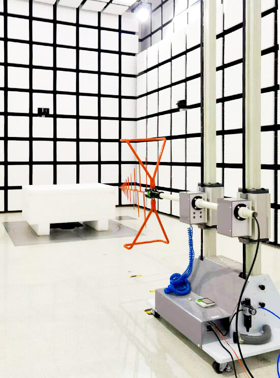
Plan Turntable and Antenna Mast Installation
A semi-anechoic chamber normally requires accurate EUT rotation and antenna positioning.
The GE Anechoic Chamber Positioning System includes the GETT-2000 turntable, GEAM-4600 antenna mast, and GEC-3 controller.
The GETT-2000 has a 2 m rotating platform and a specified maximum load of 1.5 tonnes.
Its flush-mounted configuration requires consideration of the chamber floor and supporting structure.
For an existing building, check whether a recessed installation is feasible or whether an alternative floor arrangement is required.
Any floor cutting or structural modification must be reviewed before construction.
The GEAM-4600 supports antenna centerline positioning from approximately 1 m to 4 m.
Its operating clearance, polarization movement, support structure, and cable routing should be included in the chamber layout.
Select the Appropriate Chamber Configuration
The choice between a semi-anechoic chamber (SAC) and a fully anechoic chamber (FAR) affects the installation.
A SAC typically has RF absorbers on the walls and ceiling while retaining a conductive ground plane.
A Fully Anechoic Chamber also incorporates absorbing materials on the floor.
This difference affects usable internal height, EUT support, access arrangements, and measurement procedures.
For some radiated emissions applications, a FAR can use different antenna positioning methods from a conventional SAC.
However, the selected configuration must meet the applicable test standard and site validation criteria.
A chamber should not be changed from SAC to FAR simply to accommodate a building restriction without reviewing its intended EMC applications.
Coordinate Power, Grounding, and Shielded Interfaces
Existing buildings may not have electrical infrastructure suitable for the planned EMC test system.
The electrical design should account for:
– Chamber lighting and auxiliary power
– EUT single-phase or three-phase supplies
– RF amplifier power requirements
– Turntable and antenna mast operation
– Control-room equipment
– Protective grounding and bonding
Power cables entering the shielding enclosure normally require appropriately specified RF filters.
Communication and control connections may require shielded feedthroughs or optical-fiber interfaces.
Additional services, such as compressed air or cooling lines, must also be considered.
Every penetration through the conductive enclosure should be identified before installation.
Adding unplanned cable openings after construction can compromise shielding effectiveness and increase modification costs.
An Electromagnetic Shielded Chamber depends on maintaining the integrity of these conductive boundaries.
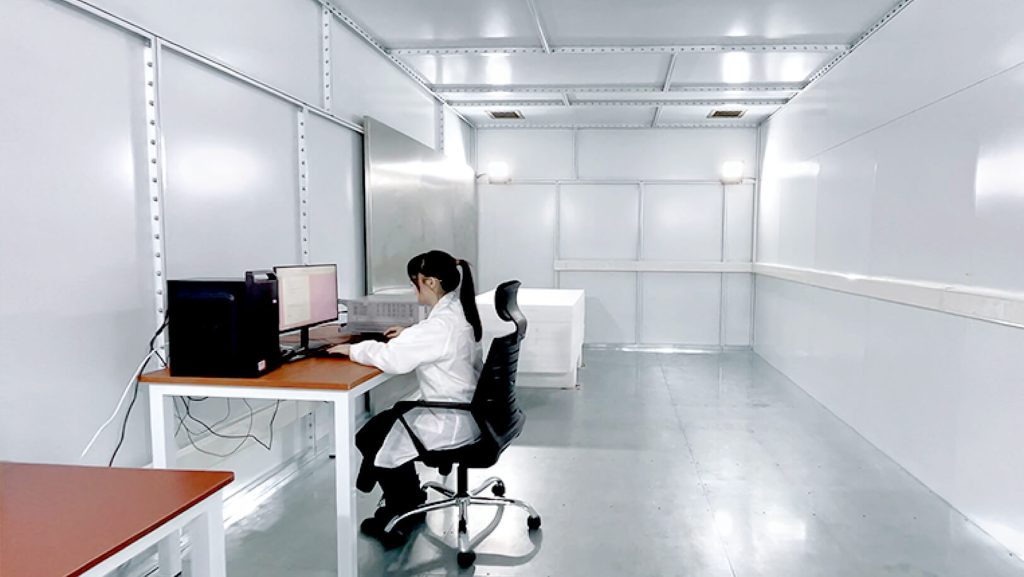
Assess HVAC and Environmental Requirements
An EMC chamber must provide suitable environmental conditions for its equipment and operators.
Existing air-conditioning capacity may be insufficient when high-power amplifiers, EUTs, lighting, and other equipment are operating simultaneously.
The HVAC assessment should include:
– Total equipment heat load
– Required airflow
– Ambient temperature and humidity
– Intake and exhaust locations
– Maintenance access
– Noise and vibration considerations
Ventilation openings crossing the shielding boundary require suitable RF shielding arrangements, such as waveguide-below-cutoff structures.
The building’s existing ductwork may need modification to connect to these interfaces.
Condensation, water leakage, and direct airflow onto sensitive equipment should also be considered.
Review Fire Protection and Building Safety
Fire protection requirements must be coordinated with the building owner, qualified fire protection specialists, and the relevant local authorities.
RF absorber materials, electrical equipment, personnel access, and high-power testing can influence the required protection strategy.
Existing sprinkler or fire detection systems may need modification.
Any associated pipes, sensors, or wiring crossing the shield must be incorporated into the RF penetration design.
Other safety considerations include emergency exits, emergency lighting, door release mechanisms, and safe shutdown procedures.
The selected arrangement must satisfy applicable building and fire codes rather than rely on a generic chamber installation specification.
Plan Construction and Performance Validation
Installing an EMC chamber in an occupied building may require coordination around normal facility operations.
Potential restrictions include working hours, dust control, material storage, noise, and temporary interruption of building services.
A practical installation sequence may include:
1. Building survey and engineering review
2. Approved structural and utility modifications
3. Shielding enclosure assembly
4. Shielding effectiveness verification
5. RF absorber installation
6. Positioning-system and equipment integration
7. Final chamber validation and acceptance
The actual sequence depends on the project design.
Shielding effectiveness testing checks the enclosure’s electromagnetic isolation.
For radiated emissions applications, site validation may also require NSA or SVSWR measurements under the applicable CISPR 16-1-4 requirements.
Radiated immunity installations may require field-uniformity calibration according to IEC 61000-4-3.
These are separate performance checks and should be included in the project acceptance plan.
Building Suitability: What Requires Further Engineering?
The following table can help identify constraints during the initial site survey.
| Existing Building Condition | Potential Impact | Required Assessment |
|---|---|---|
| Insufficient ceiling clearance | Restricted chamber height | Reconsider layout or chamber configuration |
| Limited floor capacity | Structural safety risk | Structural engineering review |
| Narrow equipment access | Installation or EUT handling problems | Delivery-route and door-size assessment |
| Existing floor services | Conflict with turntable installation | Utility survey and floor design review |
| Limited electrical capacity | Insufficient equipment supply | Electrical load assessment |
| Inadequate HVAC | Excessive operating temperature | Heat-load and ventilation assessment |
| Fixed fire protection | Conflict with shielding layout | Fire protection redesign and approval |
| Limited service access | Difficult maintenance | Equipment and maintenance layout review |
A standard chamber may be suitable when the available space, structure, and building services meet the required conditions.
Where these cannot be accommodated, a customized chamber configuration or building modification may be necessary.
Pre-Installation Site Survey Checklist
Before approving an EMC chamber installation in an existing facility, confirm:
– Intended EMC testing standards and EUT requirements
– Required chamber type and test distance
– Available internal building dimensions
– Structural loading and floor condition
– Delivery and equipment access routes
– RF shielded door dimensions
– Turntable and antenna mast requirements
– Electrical supply and protective grounding
– HVAC capacity and shielded ventilation
– Power, data, and utility penetrations
– Fire protection and safety approvals
– Control-room and maintenance space
– Site validation and acceptance requirements
A documented site survey should form part of the chamber specification before equipment procurement and construction begin. This allows the laboratory, building engineer, and EMC chamber supplier to resolve installation constraints while design changes are still practical.