A comb generator is useful in an EMC laboratory when engineers need to check whether a radiated or conducted emissions measurement system is producing consistent results. It generates repeatable RF signals at regular frequency intervals, providing a reference that can be measured before routine testing or after changes to the equipment setup.
Its main value is EMC measurement system verification. A comb generator can help identify receiver problems, damaged RF cables, preamplifier gain changes, incorrect instrument settings, and changes in a test site’s response.
Unlike formal calibration equipment, a comb generator is commonly used for comparison against previously established reference measurements. It provides a practical way to detect changes between scheduled calibrations and site validation procedures.
What Is a Comb Generator and How Does It Work?
A comb generator produces a series of discrete spectral lines separated by a defined frequency interval.
For example, a generator with 5 MHz spacing produces signals at frequencies such as 30 MHz, 35 MHz, 40 MHz, and 45 MHz, provided these frequencies fall within its operating range.
On a spectrum analyzer, these signals appear as regularly spaced peaks resembling the teeth of a comb.
Two configurations are commonly used in EMC laboratories:
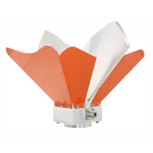
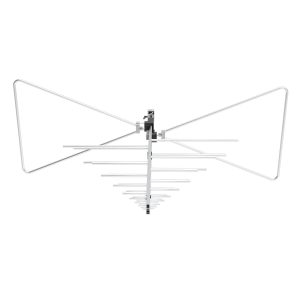
– Radiated comb generators: Transmit reference signals through an antenna for checking radiated emissions measurement systems.
– Conducted comb generators: Deliver reference signals through an electrical interface for checking conducted emissions measurement chains.
Both use repeatable signals, but their connection methods and applications differ.
When Should an EMC Laboratory Use a Comb Generator?
A comb generator is particularly useful when a laboratory needs to determine whether its measurement setup has changed since a previous test.
Typical situations include:
| Laboratory Situation | How a Comb Generator Helps |
|---|---|
| Before radiated emissions testing | Checks the response of the receiving system |
| After replacing an RF cable | Detects changes in the measurement chain |
| After preamplifier maintenance | Checks for unexpected gain differences |
| Between site validation intervals | Monitors measurement-system consistency |
| When two test sites disagree | Provides a common reference source |
| After modifying a chamber | Helps identify changes requiring investigation |
| Before conducted emissions testing | Checks LISN and receiver signal paths using a suitable conducted model |
A comb generator is most valuable when the laboratory has already established a reliable baseline and can reproduce the same measurement conditions.
Daily Verification of Radiated Emissions Test Systems
Radiated emissions measurements depend on several components working together:
Reference Source → Receiving Antenna → RF Cable → Preamplifier → EMI Receiver
A fault in any part of this chain can affect the final result.
For example, a damaged coaxial connector may introduce additional insertion loss without producing an obvious equipment fault.
A routine comb generator check can reveal the change.
In a Standard 3m Method Anechoic Chamber, engineers can position a radiated reference source at a documented location and measure selected frequencies using the normal receiving system.
The same antenna polarization, height, distance, receiver settings, and cable configuration should be used for subsequent checks.
Consistent geometry is essential because changes in antenna position or surrounding reflections may affect the measured signal independently of equipment performance.
Checking Conducted Emissions Measurement Systems
Conducted emissions testing uses a different measurement arrangement, commonly involving a Line Impedance Stabilization Network (LISN), EMI receiver, RF cables, and a transient limiter where required.
A suitable conducted comb generator can provide a repeatable signal through the LISN measurement path.
The 1313-C30M Comb Generator is designed for this application.
Its specifications include:
– Frequency range: 100 kHz–30 MHz
– Selectable frequency spacing: 100 kHz or 500 kHz
– Conducted reference signal output
– Battery-powered operation
– Compatible LISN connection options

A measurement using this source can help identify changes in the LISN-to-receiver signal path.
However, the test connection must follow the manufacturer’s instructions and the applicable electrical safety requirements.
For background on LISN operation, see How LISN Works in EMC Testing.
Which Comb Generator Is Suitable for Radiated EMC Testing?
The required frequency range and signal spacing determine which reference source is suitable.
GE offers two radiated reference signal sources for different frequency regions.
1313-C5M1G: Lower-Frequency Radiated Checks
The 1313-C5M1G Comb Generator covers 5 MHz to 1 GHz with 5 MHz frequency spacing.
It incorporates a radiating antenna and operates from an internal battery.
This configuration is suitable for monitoring radiated emissions measurement systems in facilities such as open-area test sites and semi-anechoic chambers.
Its relatively close spectral spacing provides multiple reference points throughout the frequency range commonly used for lower-frequency radiated emissions measurements.
1313-C250M18G: High-Frequency Radiated Checks
The 1313-C250M18G Comb Generator covers 1 GHz to 18 GHz with 250 MHz spacing.
According to its product specifications, it provides:
– Frequency stability: 20 ppm
– Amplitude stability: ±0.1 dB
– Typical time stability: less than 1 dB over 12 months
– Integrated radiating antenna
– Battery-powered operation

It is intended for routine reference measurements in OATS, SAC, and FAC environments.
The appropriate model should be selected according to the frequencies that need monitoring, rather than assuming one generator covers the complete EMC measurement range.
How to Establish a Comb Generator Reference Baseline
A comb generator becomes useful for long-term monitoring only after the laboratory establishes repeatable reference data.
A practical procedure includes:
Step 1: Confirm the Measurement System
Check instrument calibration status, antenna connections, RF cables, receiver settings, and reference-source battery condition.
Step 2: Fix the Source Position
For radiated measurements, record the source location, orientation, height, and distance from the receiving antenna.
Step 3: Select Reference Frequencies
Choose representative comb lines across the relevant frequency range, including frequencies where the measurement system has previously shown sensitivity or stability problems.
Step 4: Record Receiver Settings
Document resolution bandwidth, detector, attenuation, preamplifier configuration, and measurement time.
Step 5: Save Baseline Results
Measure the selected frequencies and record the received levels. Repeat the setup where practical to establish normal measurement variation.
Step 6: Define Investigation Limits
Set laboratory-specific warning or investigation limits using observed repeatability, reference-source stability, measurement uncertainty, and operational requirements.
These limits should not be confused with EMC product emission limits.
How to Interpret Changes in Reference Measurements
Consider a laboratory monitoring a selected comb generator frequency.
| Measurement | Recorded Level |
|---|---|
| Established baseline | 55.0 dBµV |
| Previous routine check | 54.8 dBµV |
| Current routine check | 52.0 dBµV |
| Change from baseline | −3.0 dB |
These are illustrative measurements, not specified acceptance limits.
A 3 dB decrease may indicate additional cable loss, reduced preamplifier gain, an antenna-positioning change, or a problem with the reference source.
The next step is to reproduce the original setup and isolate individual components.
If several reference frequencies change by similar amounts, investigate components shared across the measurement chain.
If only a narrow frequency region changes, examine frequency-dependent components, connections, and possible environmental influences.
A change does not automatically prove that the chamber has failed.
Can a Comb Generator Detect Anechoic Chamber Problems?
A comb generator can help identify unexpected changes in the measured response of an EMC test site.
For example, readings may change after absorber replacement, equipment relocation, or modification of the chamber’s internal configuration.
Reference measurements can help engineers determine whether further investigation is needed.
This can be useful for a Fully Anechoic Chamber or a semi-anechoic chamber used for radiated emissions measurements.

However, comb generator checks do not replace NSA, SVSWR, or other formal site validation procedures required by the applicable standards.
They are monitoring tools, not independent proof that a test site satisfies its complete compliance requirements.
Comb Generator vs. Calibration: What Is the Difference?
A comb generator check verifies whether the measurement setup responds consistently to a repeatable reference source.
Formal calibration establishes specified instrument characteristics and associated measurement uncertainty through an appropriate calibration procedure.
Site validation evaluates whether an EMC measurement environment satisfies relevant performance requirements.
These activities serve different purposes.
A comb generator may reveal a problem between scheduled calibration intervals, but it cannot independently establish antenna factors, EMI receiver accuracy, or complete chamber compliance.
Similarly, a general radiated comb generator should not be treated as a substitute for a dedicated shielding-effectiveness test according to an applicable method such as IEEE 299.
Practical Decision Guide for EMC Laboratories
Use a comb generator when the main question is:
“Is my EMC measurement system responding consistently compared with its established baseline?”
Choose a radiated reference source when checking antennas, cables, preamplifiers, receivers, and repeatability of the radiated measurement arrangement.
Choose a suitable conducted reference source when checking the LISN-based conducted emissions measurement path.
If the objective is to determine absolute instrument accuracy, antenna factor, formal site compliance, or shielding attenuation, use the appropriate calibration or validation procedure instead.
Comb Generator Verification Checklist
Before accepting a routine reference measurement, confirm:
– Correct generator type and frequency range
– Adequate reference-source battery condition
– Consistent source position and orientation
– Correct receiving antenna configuration
– Unchanged RF cable connections
– Correct preamplifier and receiver settings
– Selected reference frequencies
– Available baseline records
– Documented measurement differences
– Defined investigation limits
– Corrective action for unexplained deviations
A well-maintained reference log gives engineers a practical way to identify measurement-chain problems before they affect customer EMC test results.