

Dual-ridged horn antennas are widely used in EMC laboratories when radiated emissions or radiated immunity tests extend into the GHz range. Compared with conventional horn antennas, the dual-ridged structure provides much wider frequency coverage while retaining directional radiation, useful antenna gain, linear polarization, and relatively low VSWR.
These characteristics make dual-ridged horn antennas suitable for high-frequency EMC testing, RF measurement, wireless device evaluation, radar testing, and microwave system development.
A typical EMC laboratory may use biconical or log-periodic antennas at lower frequencies and switch to a dual-ridged horn antenna above approximately 1 GHz. The exact transition frequency depends on antenna factor, gain, chamber performance, test distance, and the applicable EMC standard.
Why Dual-Ridged Horn Antennas Have Wide Bandwidth
A conventional horn antenna is usually designed for a limited waveguide band. Its gain and directional pattern can be excellent, but the operating bandwidth is relatively narrow.
A dual-ridged horn antenna introduces two conductive ridges inside the waveguide section. These ridges change the electromagnetic field distribution and lower the effective cutoff frequency, allowing the antenna to operate across a much wider frequency range.
For EMC applications, this provides several practical advantages:
* One antenna can cover multiple microwave bands.
* Fewer antenna changes are required during automated tests.
* Directional gain improves high-frequency receiving sensitivity.
* Lower VSWR reduces reflected power during immunity testing.
* Linear polarization supports horizontal and vertical measurements.
* Broadband coverage simplifies calibration and test setup.
The antenna still needs to be selected according to the complete system. Frequency range alone does not confirm whether it has sufficient gain, power handling, or beamwidth for the intended test.
Radiated Emissions Testing Above 1 GHz
Modern electronic equipment contains high-speed processors, memory interfaces, wireless modules, switching power supplies, and digital communication ports. Even when the main operating frequency is below 1 GHz, harmonics and switching noise may extend several gigahertz higher.
Common sources of high-frequency radiated emissions include:
* Processor and clock harmonics
* HDMI and display interfaces
* Ethernet ports and cables
* Wi-Fi and Bluetooth modules
* Cellular communication circuits
* Automotive radar electronics
* High-speed data buses
* Switching regulators
* Shielding gaps and enclosure seams
During radiated emissions testing, a dual-ridged horn antenna receives these signals and sends them to an EMI receiver or spectrum analyzer.
Its directional gain helps improve measurement sensitivity at higher frequencies, where free-space path loss and RF cable loss become more significant. The antenna must be aimed correctly toward the equipment under test because its main beam is narrower than that of a biconical antenna.
An automated turntable and antenna mast system can rotate the EUT, adjust antenna height, change polarization, and maintain antenna boresight during the search for maximum emissions.
Antenna Factor and Receiving Sensitivity
For radiated emissions measurements, the antenna factor is used to convert the voltage measured at the receiver input into electric field strength.
The final result normally includes:
* EMI receiver reading
* Antenna factor
* RF cable loss
* Preamplifier gain
* Other system correction factors
A lower antenna factor generally improves receiving sensitivity because the same incident field produces a higher voltage at the antenna output.
The antenna factor is not constant across a wide frequency range. EMC software should therefore use the calibration data supplied for the individual antenna rather than applying one average value.
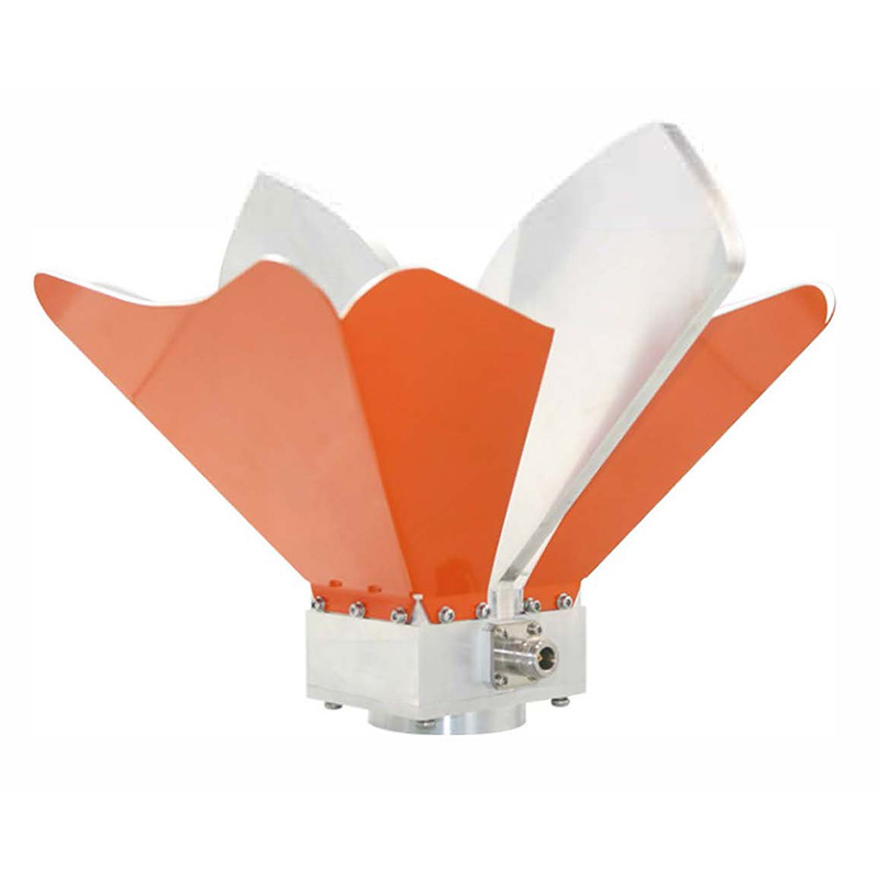
The OBH-08180 broadband dual-ridged horn antenna covers 0.8 GHz to 18 GHz. It provides gain from approximately 5 to 14 dBi, typical VSWR of 1.5:1, and maximum power handling of 1500 W.
Its wide range allows one antenna to support many common high-frequency radiated emissions and immunity tests without changing equipment at every microwave band.
Radiated Immunity Testing
In radiated immunity testing, the dual-ridged horn antenna is connected to an RF signal generator and power amplifier. The antenna transmits electromagnetic energy toward the EUT until the required field strength is produced over the calibrated test area.
The antenna is suitable for immunity testing because it provides:
* Directional RF transmission
* Broadband frequency coverage
* Useful gain
* High RF power capacity
* Linear polarization
* Relatively low reflected power
The required amplifier power depends on antenna gain, VSWR, test distance, cable loss, chamber loading, and target field strength.
A higher-gain antenna can produce a stronger field with less amplifier power, but higher gain often means narrower beamwidth. If the beam is too narrow, the field may not cover the complete EUT or calibrated field-uniformity area.
The best antenna is therefore not always the model with the highest gain. Gain and beamwidth must be considered together.
VSWR and Power Transfer
VSWR shows how closely the antenna input impedance matches the 50-ohm RF system.
When VSWR is high, part of the forward RF power is reflected toward the amplifier. This reduces the power delivered to the antenna and may cause:
* Lower field strength
* Amplifier foldback
* Amplifier shutdown
* Additional cable and connector heating
* Unstable field calibration
* Higher amplifier power requirements
A typical VSWR of 1.5:1 represents much lower reflected power than a VSWR of 3:1.
Because VSWR changes with frequency, the complete VSWR curve is more useful than one typical catalog value. The worst frequency point may determine the amplifier size required for the complete immunity test range.
Power Handling
Dual-ridged horn antennas are available with very different power ratings.
The required power rating depends on:
* Maximum amplifier output
* Required field strength
* Continuous or pulsed operation
* Modulation type
* Duty cycle
* Test duration
* VSWR
* Connector type
* Cable power capacity
The antenna should not be operated continuously at its absolute maximum rating. Practical margin is needed for impedance variation, calibration correction, amplifier overshoot, and future test requirements.
The complete RF path must also support the applied power. A high-power antenna does not protect a lower-rated cable, connector, adapter, RF switch, or directional coupler.
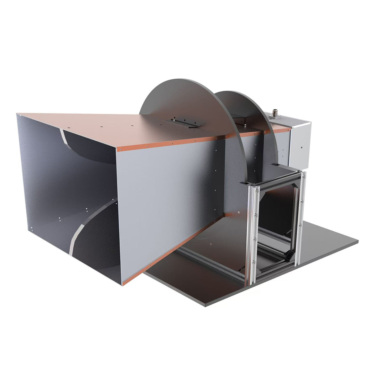
For wider low-frequency coverage, the OBH-460-HG ultra-wide-band dual-ridged horn antenna operates from 0.4 GHz to 6 GHz. It is suitable for applications that require wide bandwidth and high field strength across UHF and lower microwave frequencies.
High-Frequency and Millimeter-Wave Applications
Some automotive, radar, satellite, aerospace, and defense applications require measurements above 18 GHz.
The OBH-180400-20 dual-ridged horn antenna covers 18 GHz to 40 GHz and provides approximately 20 dBi gain.
Typical applications include:
* Automotive radar testing
* Satellite communication equipment
* Microwave component measurements
* Aerospace and defense systems
* High-frequency radiated emissions
* Antenna pattern measurements
* Millimeter-wave research
At these frequencies, cable and connector performance becomes critical. Cable insertion loss, connector torque, adapter loss, bending radius, and cable movement can all affect the measured result.
An antenna rated to 40 GHz does not make the complete EMC system suitable for 40 GHz testing. The chamber absorbers, receiver, cable system, connectors, amplifiers, and calibration method must support the same range.
Beamwidth and Antenna Positioning
Dual-ridged horn antennas concentrate energy into a directional beam.
For radiated emissions testing, this directionality improves sensitivity toward the EUT and reduces reception from unwanted directions.
For radiated immunity testing, the beam must cover the complete calibrated test area. A narrow beam may produce a strong field at the center but insufficient field strength near the edges.
The practical setup must balance:
* Antenna gain
* E-plane and H-plane beamwidth
* Test distance
* EUT dimensions
* Chamber size
* Required field strength
* Available amplifier power
The antenna should be mounted securely and aligned with the center of the EUT or field-uniformity area. Horizontal and vertical polarization changes should not shift the antenna away from the intended boresight.
Using Dual-Ridged Horn Antennas in an Anechoic Chamber
The antenna must be selected together with the chamber and positioning system.
A suitable chamber should provide:
* Adequate antenna-to-EUT distance
* Absorber performance across the required frequency range
* Stable antenna mounting
* Clear boresight toward the EUT
* Low chamber background noise
* Controlled RF cable routing
* Sufficient turntable and mast movement
A fully anechoic chamber uses absorbers on the walls, ceiling, and floor to reduce reflections. A semi-anechoic chamber normally retains a conductive ground plane.
Chamber validation must include the frequencies at which the horn antenna will be used. Wide antenna bandwidth cannot compensate for inadequate absorber performance or uncontrolled chamber reflections.
Selecting a Dual-Ridged Horn Antenna
Before selecting a model, confirm:
* Minimum and maximum test frequency
* Radiated emissions, immunity, or both
* Antenna factor and calibration data
* Gain across the complete band
* Typical and maximum VSWR
* Continuous and pulse power ratings
* Beamwidth
* Connector type
* RF cable loss
* Antenna dimensions and weight
* Mast load capacity
* Chamber measurement distance
* Required field-uniformity area
The EMC antenna product range includes dual-ridged horn, log-periodic, hybrid, biconical, and loop antennas for different EMC and RF testing requirements.










