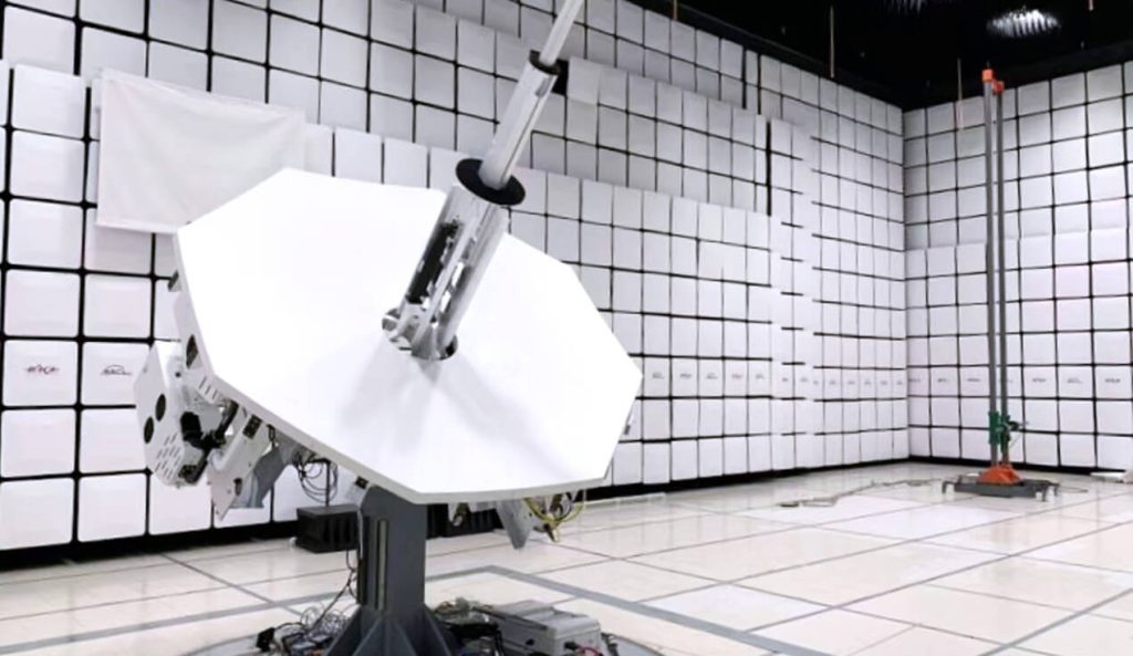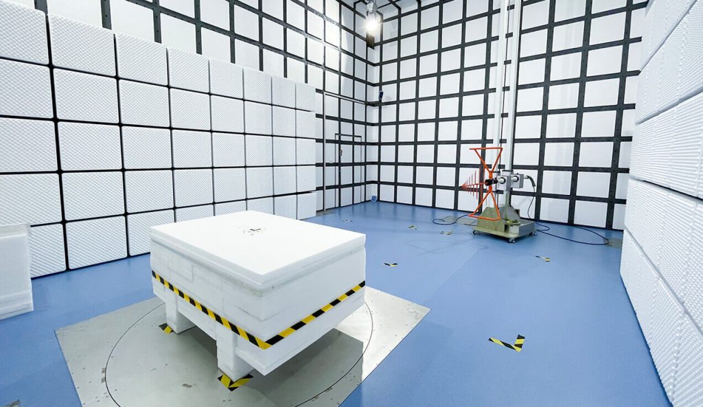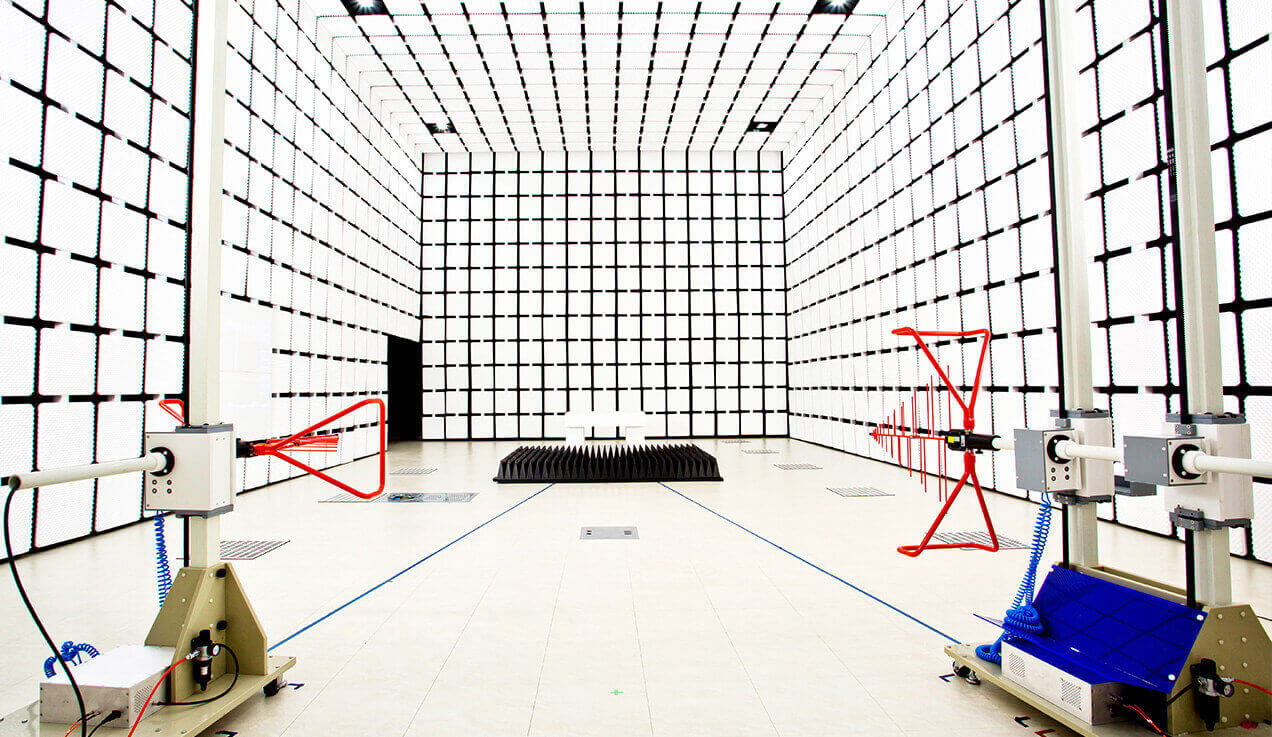
Anechoic Chamber Introduction
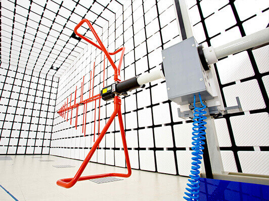
A 10m anechoic chamber provides a controlled electromagnetic compatibility (EMC) testing environment for large equipment under test (EUTs) and applications requiring a 10-meter radiated emissions measurement distance.
GE EMC offers configurable 10m chamber solutions based on applicable test standards, EUT dimensions, antenna positioning, RF absorber design, and available facility space. Depending on project requirements, the chamber can be designed for radiated emissions testing and radiated immunity testing with appropriate equipment and field calibration.
The chamber configuration, usable test volume, and performance requirements are determined during the engineering design process.
Key Test Parameters
| Test Distance | 10m (distance from EUT to receiving antenna) |
|---|---|
| Frequency range | Standard testing: 30 MHz ~ 40 GHz (extendable to millimeter wave bands with customized absorbers) Low-frequency testing: Supports 150 kHz ~ 1 GHz (requires ferrite + pyramidal absorber combination) |
| Shielding effectiveness | Low frequency (14 kHz ~ 1 MHz): ≥ 90 dB High frequency (1 MHz ~ 40 GHz): ≥ 120 dB Extreme bands (e.g., 100 GHz): ≥ 70 dB (requires special high-frequency absorbers) |
| Quiet zone | Effective test area diameter/height: 3~5m (larger quiet zone suitable for big equipment testing) |
| Grounding Resistance | Standard: IEC 60364-6 (GB/T 16895.23) Requirement: ≤ 4Ω |
| Insulation Resistance | Standard: IEC 60364-6 (GB/T 16895.23) Requirement: ≤ 2 MΩ |
| Field uniformity | ≤ ±3 dB variation within 4m×4m area (compliant with IEC 61000-4-3) |
| Influence Assessment of Radiated Emission Test Table | Compliance Standards: CISPR 16-1-4, ANSI C63.4 Requirement: The influence assessment results of the radiated emission test table must be incorporated into the uncertainty evaluation of radiated emission measurements |
| Ambient noise level | At least 10 dB below test limits (higher sensitivity for weak signal detection) |
Structural Design Parameters
| Chamber Dimensions | Length: 20~25m (meets test distance and quiet zone requirements) Width: 12~15m (ensures quiet zone integrity) Height: 10~12m (accommodates large antenna movement and quiet zone) |
|---|---|
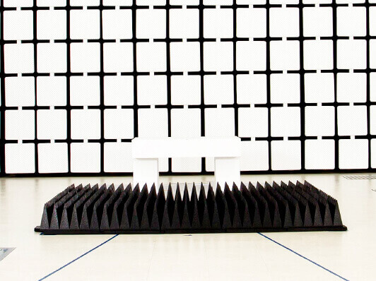
| Absorbing Materials | Type:Ferrite tiles (30 MHz ~ 1 GHz) + carbon-based pyramidal absorbers (1 GHz ~ 40 GHz) Low-frequency optimization: Double-layer ferrite + pyramidal composite structure (enhances low-frequency absorption) High-frequency optimization: Absorber height 2~3m (reduces reflection, improves mmWave performance) |
| Shielding Structure | Material: Double-layer copper or galvanized steel plates welded, with metal conductive adhesive + beryllium copper finger gaskets at joints Shielded door: Hydraulically-driven hermetic door with integrated RF filtering and EMC sealing |
| Turntable and antenna system | Turntable diameter: 3~5m, load capacity ≥ 3~5 tons (supports complete vehicle testing) Antenna polarization: Fully automated multi-axis control (horizontal/vertical/circular) Antenna tower: Adjustable height range 2~8m (meets far-field testing requirements) |
Compliance Standards
| EMC testing standards | CISPR 25 (GB/T 18655 vehicle electronics radiated emissions) CISPR 32/35 (GB/T 9254.1/2 multimedia equipment) ISO 11451-2 (vehicle electronics radiated immunity) MIL-STD-461G (GJB 151C military equipment) |
|---|
Auxiliary Systems
| Power supply and filtering | Power: Three-phase independent filtered system (single/three-phase optional), harmonic suppression ≥ 40 dB
Fiber optic transmission: Signals penetrate chamber via fiber (avoids cable-induced interference) |
|---|---|
| Environmental control | Temperature: 18~25℃ (±1℃ precision control for high-accuracy testing) Humidity: 20%~60% RH (prevents static and absorber aging) |
| Safety systems | IR monitoring + emergency exhaust system (prevents overheating/gas leakage) Full-band RF radiation monitor (real-time display of EM leakage) |
Typical Applications
| Radiated emissions/immunity testing for complete vehicles and components | |
|---|---|
| High-frequency EMC testing for aerospace equipment (e.g., avionics) | |
| mmWave band (24~40 GHz) certification for 5G/6G communication devices | |
| EMC testing for large industrial equipment (e.g., wind power converters, high-speed rail electronics) |
Large Industrial Equipment: Radiated emissions testing for large electrical cabinets, industrial machinery, power electronics, and integrated equipment systems.
Automotive and Vehicle Systems: EMC testing projects involving vehicles or large automotive systems, with chamber dimensions, turntable capacity, and test arrangements determined by the applicable standards.
Aerospace and Electronic Systems: EMC evaluation of large electronic assemblies, control systems, and equipment requiring greater test volume and antenna clearance.
EMC Testing Laboratories: Customized chamber configurations for laboratories requiring a 10m radiated emissions test distance, with optional radiated immunity testing capability.
When Should You Choose a 10m Anechoic Chamber?
A 10m anechoic chamber is generally considered when the required measurement distance, EUT dimensions, or test arrangement cannot be adequately accommodated in a smaller chamber.
Compared with 3m and 5m chambers, a 10m configuration provides more space for large EUTs, antenna positioning, and complex cable arrangements. However, it also requires greater floor space, ceiling height, absorber volume, and mechanical capacity.
A larger test distance does not automatically provide better measurement accuracy. The selection should be based on applicable EMC standards, chamber validation requirements, test volume, and facility constraints.
For a detailed comparison, refer to our 3m, 5m, and 10m Anechoic Chamber Selection Guide.
FAQs About 10m Anechoic Chambers
What is a 10m anechoic chamber used for?
A 10m anechoic chamber is used for EMC testing applications requiring a 10-meter measurement distance, particularly for large electrical equipment and systems. The chamber provides a controlled environment for radiated emissions measurements.
Can a 10m anechoic chamber support radiated immunity testing?
Yes, a 10m chamber can be configured for radiated immunity testing when the required RF generating system, field uniformity, calibration, and safety requirements are included in the chamber design.
How is the size of a 10m anechoic chamber determined?
Chamber dimensions depend on the test distance, maximum EUT size, antenna movement, absorber clearance, turntable requirements, and available building space. The final dimensions should be established during engineering design.
What information is needed for a 10m anechoic chamber quotation?
The main information includes applicable EMC standards, required frequency range, EUT dimensions and weight, testing requirements, and available installation space. Additional requirements may include turntable capacity, antenna mast configuration, and auxiliary systems.
Request a Quotation for a 10m Anechoic Chamber
Planning a 10m EMC testing chamber for your laboratory?
Share your testing standards, EUT dimensions, required frequency range, and available installation space. GE EMC can discuss a customized chamber configuration and provide a quotation based on your project requirements.