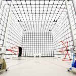


The selection of a 3M, 5M, or 10M anechoic chamber is a fundamental engineering decision in EMC laboratory planning. Test distance directly influences EMC measurement validity, quiet zone performance, facility constraints, and lifecycle cost, and should therefore be treated as a primary design parameter rather than a secondary specification.
In practical EMC testing, test distance is inseparable from the physical dimensions of the equipment under test, antenna separation requirements, and the ability to establish a compliant quiet zone. A 3M configuration is commonly applied to small and medium-sized electronic products, including consumer electronics, wireless devices, and compact industrial equipment. A 5M configuration is typically introduced when equipment size or cable layout exceeds the spatial tolerance of a 3 m setup while remaining below the scale that necessitates a full 10M range. A 10M configuration is generally reserved for large systems where far-field conditions and spatial uniformity cannot be achieved at shorter distances.
From an engineering decision standpoint, chamber selection should follow a minimum-compliance logic rather than a maximum-capability approach. If the equipment under test can be evaluated at 3M while maintaining antenna clearance and quiet zone requirements, increasing the distance provides limited technical benefit. Transition to 5M or 10M should occur only when compliance, repeatability, or measurement stability cannot be achieved at shorter distances.
The functional distinctions between common chamber distances can be summarized as follows.
For 3M anechoic chambers, the primary advantages are compact facility requirements, lower structural load, and reduced installation and operating cost. These chambers are well suited for high-throughput testing of small to mid-sized products where space efficiency and measurement repeatability are priorities. The main limitation is reduced tolerance for large equipment dimensions and complex cable arrangements.

For 5M anechoic chambers, increased spatial flexibility allows accommodation of larger products and more complex test setups. This distance often represents a compromise between technical capability and facility constraints. However, cost and complexity increase disproportionately compared to 3 m systems due to higher absorber volume, shielding mass, and mechanical precision requirements.

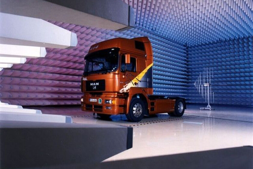
For 10M anechoic chambers, the defining characteristic is the ability to support large systems and full-scale equipment testing. These chambers impose significant demands on building structure, ceiling height, foundation strength, and HVAC capacity. While technically necessary for certain applications, they present the highest risk of over-specification when selected without a clear and justified product requirement.

In addition to test distance, several key engineering considerations should be evaluated during chamber selection.
Equipment under test envelope: The physical size of the EUT, including fixtures, turntables, and cabling, defines the minimum feasible test distance more reliably than nominal product dimensions alone.
Quiet zone requirements: Required quiet zone size and uniformity must be achievable within the selected chamber geometry using appropriate absorber performance for the intended frequency range.
Facility constraints: Available floor area, ceiling height, structural load capacity, and vibration sensitivity often limit feasible chamber size before technical requirements do.
Frequency range relevance: Chamber performance should be aligned with actual regulatory test frequencies rather than hypothetical future needs to avoid unnecessary absorber depth and cost.
Operational efficiency: Throughput, setup time, and ease of access can have a greater impact on long-term productivity than maximum chamber capability.
Lifecycle cost: Energy consumption, maintenance, calibration effort, and absorber replacement scale with chamber volume and persist throughout the facility’s service life.
Several recurring pitfalls are observed in chamber selection projects. One common issue is underestimating facility integration constraints. Chamber systems require additional space for control rooms, absorber access, cable routing, and safety clearance. Facilities that appear adequate based on internal chamber dimensions alone may be unsuitable once structural and environmental requirements are considered, particularly for 10M installations.
Another frequent misunderstanding is assuming that increasing test distance inherently improves measurement accuracy. Quiet zone quality is determined by absorber performance, chamber geometry, and antenna positioning accuracy rather than distance alone. An oversized chamber with insufficient absorber depth or suboptimal layout can produce inferior results compared to a properly optimized smaller chamber.
Over-specification of frequency range is also a persistent inefficiency. Designing chambers to support frequency bands that exceed actual testing requirements increases absorber depth, chamber volume, and cost without delivering corresponding compliance benefit. This is often driven by hypothetical future needs rather than documented product roadmaps.
The engineering objective should therefore be to identify the minimum chamber configuration that consistently satisfies regulatory and measurement requirements for the intended scope of testing. Oversizing increases capital expenditure, operational cost, and facility complexity while offering limited technical advantage for many applications.
This guidance is intended to support technically defensible decision-making across EMC laboratories, system integrators, and academic institutions. Because it is based on underlying measurement principles rather than specific limit values or product specifications, it remains applicable across standards revisions and extended facility lifecycles.