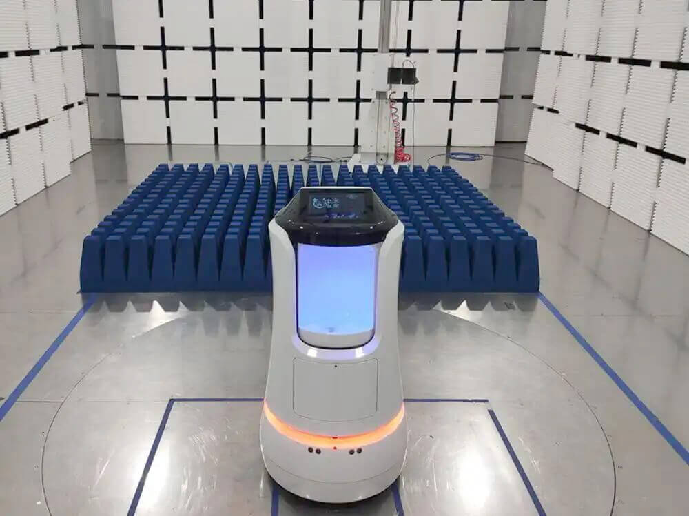
An EMC shielded room is designed to isolate sensitive electronic equipment and test environments from external electromagnetic interference. However, its shielding performance depends on more than the metal enclosure itself.
RF doors, conductive joints, power filters, cable penetrations, ventilation panels, and grounding connections must continue working as intended throughout the room’s service life.
Over time, mechanical wear, corrosion, contamination, and unauthorized modifications can reduce shielding effectiveness, even when the room appears structurally sound.
A regular EMC shielded room maintenance program helps identify these problems before they affect laboratory measurements, equipment operation, or EMC compliance testing.
Why Shielded Room Maintenance Matters
The primary function of an electromagnetic shielded chamber is to provide electromagnetic isolation between its internal environment and the surrounding facility.
Shielding effectiveness depends on the continuity of the conductive enclosure and the performance of its openings and interfaces.
A small gap around a door, a damaged RF gasket, or an improperly installed cable penetration can create a leakage path.
Common signs of deteriorating shielding performance include:
– Higher background RF noise inside the room
– Unexpected external radio signals during measurements
– Reduced repeatability between EMC tests
– RF leakage around doors or penetrations
– Differences between current and previous shielding measurements
These symptoms do not always indicate a structural failure. They may result from a single deteriorated contact or recently modified interface.
1. Inspect RF Shielded Doors Regularly
The RF shielded door is usually one of the most frequently operated components.
Unlike fixed metal panels, the door must maintain electrical contact with its frame through repeated opening and closing.
Depending on the design, shielding doors may use conductive fingerstock, knife-edge contacts, compression gaskets, or mechanical locking systems.
Maintenance should focus on:
– Door-frame alignment
– Conductive contact condition
– Fingerstock deformation
– Gasket wear
– Dirt accumulation
– Locking mechanism operation
– Hinges and door movement
A door that closes normally may still have insufficient RF contact pressure at one section of its perimeter.
Uneven compression can create a localized shielding weakness.
Inspect the entire sealing surface, particularly the corners and lower threshold where dust and mechanical damage are common.
2. Clean and Protect Conductive Door Contacts
Conductive door contacts must remain clean to maintain reliable electrical continuity.
Dust, oxidation, debris, and unsuitable cleaning materials can interfere with the connection between the door and frame.
For routine maintenance:
– Remove loose debris from contact surfaces.
– Use cleaning methods approved by the door manufacturer.
– Inspect contacts for discoloration or corrosion.
– Check for bent or broken fingerstock.
– Replace damaged sealing components when necessary.
Avoid abrasive cleaning methods that could remove conductive plating or damage the contact surface.
Lubricants should only be applied where specified by the manufacturer. Ordinary oil or grease may contaminate RF contact areas.
When replacing conductive gaskets, use components compatible with the original shielding design rather than selecting replacements based only on physical dimensions.
3. Check Shielding Panels and Conductive Joints
The walls, ceiling, and floor of an RF shielded room form a continuous conductive enclosure.
Depending on construction, panels may be welded, bolted, or assembled using conductive joint materials.
Over time, the enclosure may be affected by:
– Mechanical impact
– Loose fasteners
– Corrosion
– Moisture ingress
– Building movement
– Unapproved drilling or modifications
Inspect visible panel joints, corners, floor connections, and areas around equipment installations.
Particular attention should be paid to locations where new electrical or mechanical equipment has been added.
A new screw hole, conduit opening, or damaged joint can compromise the shielding boundary.
Any structural repair should restore the original conductive continuity using an appropriate shielding repair method.
4. Maintain RF Power-Line Filters
Electrical power must enter the shielded room without creating an uncontrolled RF path.
This is normally achieved through appropriately rated power-line filters mounted at the shielding boundary.
A damaged filter, loose mounting connection, or improper wiring modification may reduce isolation.
During maintenance, check:
– Filter enclosure condition
– Mounting integrity
– Signs of overheating
– Corrosion around mounting surfaces
– Cable strain
– Changes to filter wiring
– Proper installation of replacement components
Electrical safety inspections should be performed by qualified personnel using appropriate isolation procedures.
An RF filter must meet both electrical safety and electromagnetic attenuation requirements.
Replacing it with an ordinary electrical noise filter without verifying shielding specifications may reduce room performance.
5. Inspect Cable Penetrations and Signal Interfaces
Every conductive cable crossing the shielded enclosure creates a potential leakage path.
Common interfaces include power cables, communication cables, coaxial RF cables, monitoring connections, and control signals.
Properly designed shielded rooms use filtered feedthroughs, shielded connectors, or suitable penetration assemblies.
Fiber-optic connections can be advantageous because optical fiber itself does not provide a conductive RF path.
During inspection, verify that:
– Penetration panels remain securely mounted.
– Connectors are not mechanically damaged.
– Unused openings remain correctly sealed.
– No unfiltered cables have been added.
– Shielded cable terminations remain intact.
A common maintenance risk is an unauthorized cable modification.
For example, routing an additional Ethernet or power cable through an existing opening without proper shielding treatment can create a new electromagnetic leakage path.
Any interface modification should be reviewed against the original shielding design.
6. Keep Ventilation Waveguides in Good Condition
EMC shielded rooms require airflow for equipment cooling and environmental control.
However, ordinary ventilation openings would compromise electromagnetic shielding.
Shielded ventilation systems commonly use honeycomb waveguide-below-cutoff panels that permit airflow while limiting RF transmission.
Maintenance should include:
– Removing accumulated dust
– Checking for blocked airflow
– Inspecting honeycomb structures
– Checking conductive mounting joints
– Looking for corrosion or deformation
– Verifying HVAC operation
Avoid damaging or painting conductive contact surfaces during cleaning or renovation.
A bent or improperly replaced ventilation panel may affect shielding even if airflow appears normal.
7. Monitor Grounding and Electrical Bonding
Grounding and bonding are important parts of electrical safety and electromagnetic system performance, but they serve different purposes.
Protective grounding provides a fault-current path for electrical safety.
Conductive bonding helps maintain electrical continuity between parts of the shielding enclosure.
Maintenance should verify that relevant bonding connections remain secure and free from corrosion.
Do not assume that a satisfactory building earth-resistance measurement proves the RF shielding is intact.
High-frequency shielding performance also depends on enclosure joints, apertures, contact geometry, and the complete conductive boundary.
Grounding and bonding inspections should follow the installation design and applicable electrical safety requirements.
8. Control Temperature, Humidity, and Corrosion
Environmental conditions can influence the long-term condition of shielding materials.
Excessive humidity may accelerate corrosion of metal surfaces and conductive contacts.
Condensation can also affect connectors, filters, electrical installations, and mechanical assemblies.
A shielded room should maintain environmental conditions suitable for its materials and installed equipment.
Recommended checks include:
– HVAC operation
– Water leakage
– Condensation
– Visible corrosion
– Temperature variation
– Humidity trends
Areas near ventilation systems, exterior walls, and shielded doors deserve particular attention.
For a combined semi-anechoic chamber, absorber damage or moisture exposure must also be addressed because absorber deterioration can affect RF reflection performance.
The relationship between these components is explained in Main Components of a Semi-Anechoic Chamber.
9. Verify Shielding Effectiveness After Important Changes
Visual inspection cannot fully determine RF shielding effectiveness.
A room may appear undamaged while experiencing electromagnetic leakage at a joint, door contact, or penetration.
Shielding effectiveness testing compares electromagnetic signal levels across the enclosure under defined measurement conditions.
The test should cover the relevant frequency range and important locations, particularly around:
– Shielded doors
– Panel joints
– Ventilation panels
– Power filters
– Cable penetrations
– Repaired sections
IEEE 299-based measurement procedures have historically been used for evaluating large electromagnetic shielding enclosures. The actual method, frequency points, and acceptance criteria should follow the applicable project specification or agreed test procedure.
Periodic testing is especially useful after door repairs, filter replacement, building modifications, or unexplained increases in ambient RF noise.
Results should be compared with previous measurements to identify performance degradation.
10. Distinguish Shielding Problems from Chamber Validation Problems
For shielded rooms used as EMC anechoic chambers, two performance aspects must be distinguished.
Shielding effectiveness evaluates isolation between the chamber interior and exterior.
NSA, SVSWR, and field uniformity evaluate different aspects of the internal test environment.
A chamber may maintain good shielding performance while its internal site characteristics change because of damaged absorbers, relocated metallic equipment, or positioning-system modifications.
Therefore, passing a shielding effectiveness test does not automatically mean the chamber still meets all radiated emissions or immunity validation requirements.
See Key Anechoic Chamber Performance Indicators: NSA, SVSWR, and Field Uniformity for the differences.
11. Establish a Preventive Maintenance Schedule
A practical maintenance program should reflect room usage, environmental conditions, door operating frequency, and previous inspection results.
A typical approach may include:
Daily or before use
– Check RF door closure and visible contact condition.
– Confirm no unauthorized cables pass through the shielding boundary.
– Look for obvious damage or unusual background noise.
Monthly
– Inspect door seals and contact surfaces.
– Check ventilation openings.
– Inspect accessible panel joints.
– Review any equipment or interface modifications.
Periodically or during planned servicing
– Inspect filters and penetration assemblies.
– Check bonding connections.
– Service mechanical door components.
– Review corrosion and environmental conditions.
– Arrange shielding effectiveness testing where required.
These intervals are examples for planning, not universal standard-mandated frequencies. The room manufacturer’s instructions and laboratory quality procedures should determine the actual schedule.
Shielded Room Maintenance Checklist
Before returning an EMC shielded room to routine use, confirm:
– RF door contacts are clean and undamaged.
– Door alignment and compression are correct.
– Shielding panel joints are secure.
– No unauthorized holes or penetrations exist.
– Power filters and feedthroughs are properly installed.
– Ventilation waveguides are unobstructed.
– Grounding and bonding connections remain secure.
– No significant corrosion or moisture damage is present.
– Repairs and modifications are documented.
– Required shielding effectiveness checks are completed.
The room’s original acceptance results should be retained as a reference for future maintenance and performance comparisons.
For laboratories planning new installations or major upgrades, From Site Planning to Validation: A Complete Guide to EMC Chamber Projects explains how shielding, filters, ventilation, and chamber validation should be coordinated from the beginning.
Maintaining an EMC shielded room is ultimately about preserving the integrity of its conductive boundary. Regular inspection, controlled modifications, and appropriate performance verification help ensure that the enclosure continues providing reliable electromagnetic isolation throughout its operating life.