Radiated emission testing is not a measurement taken from one fixed EUT position and one fixed antenna height.
Electronic equipment rarely radiates electromagnetic energy equally in every direction. At the same time, the signal arriving at the receiving antenna can change significantly as the antenna moves vertically.
For this reason, radiated emissions testing commonly combines EUT rotation, antenna height scanning, and horizontal/vertical antenna polarization to search for the maximum emission level.
These movements are not simply mechanical details of an EMC chamber. They directly affect whether the measurement system finds the worst-case radiated disturbance produced by the equipment under test.
A typical automated EMC positioning system uses a turntable to rotate the EUT and an antenna mast to control antenna height and polarization while the EMI receiver records the corresponding signal level.
Technical Summary
* EUT rotation is used to identify the direction that produces the highest radiated emission.
* Antenna height scanning helps locate the maximum received level caused by direct and reflected signal paths in semi-anechoic chambers and open-area test sites.
* Horizontal and vertical polarization must also be checked because emission strength depends on the orientation of the radiating structure.
* The worst-case result is normally determined by the combination of frequency, EUT angle, antenna height, and antenna polarization.
* Automated turntables and antenna masts improve repeatability and allow the test system to return accurately to the position where the maximum emission was found.
Why a Fixed EUT Position Is Not Enough
An electronic product can contain many different RF radiation sources:
* PCB traces
* High-speed clocks
* Power converters
* Display interfaces
* Ventilation openings
* Enclosure seams
* Power cables
* Ethernet and communication cables
* Internal wiring harnesses
Each source can have a different radiation pattern.
For example, an emission produced mainly by an external cable may be strongest when that cable faces the receiving antenna. Another emission may come from a PCB or enclosure opening located on a different side of the product.
If the EUT is measured only from the front, the laboratory may record a level several decibels below the actual maximum.
Rotating the EUT allows the measurement antenna to evaluate radiation from different physical orientations and identify the angle that produces the highest disturbance.
How EUT Rotation Finds the Maximum Radiation Direction
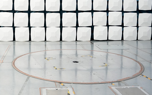
During a radiated emission scan, the turntable can rotate the EUT through a complete 360-degree range.
The measurement system monitors the emission level while the product changes orientation relative to the antenna.
The maximum angle is not necessarily:
* 0°
* 90°
* 180°
* 270°
A cable, PCB trace, enclosure seam, or other radiating structure may produce its strongest coupling at an intermediate angle such as 35°, 125°, or 220°.
This is why an automated EMC turntable is useful.
During a fast pre-scan, the table may rotate continuously while the EMI receiver identifies frequencies and approximate angles with high emissions. The system can then return to those angles for more detailed measurements.
The GETT-2000 turntable used in the positioning system supports up to 360° rotation with positioning accuracy suitable for returning to previously identified EUT orientations.
Repeatable angular positioning becomes especially important during EMC troubleshooting. If an emission fails at a particular angle, the engineer needs to reproduce the same position after changing a cable, filter, shielding component, or PCB design.
Why Antenna Height Changes the Measured Level
EUT rotation searches for the strongest radiation direction. Antenna height scanning solves a different problem.
In a semi-anechoic chamber or open-area test site, the receiving antenna does not receive only the direct electromagnetic wave from the EUT.
It can also receive energy reflected from the conductive ground plane.
The direct and reflected signals arrive at the antenna with different path lengths and phases. Depending on antenna height and frequency, they may:
* Reinforce each other
* Partially cancel
* Produce a local maximum
* Produce a local minimum
As the antenna moves vertically, the relationship between these two signal paths changes.
A measurement performed at only one fixed antenna height could therefore occur near a cancellation point and significantly underestimate the actual radiated emission.
Height scanning is used to search for the antenna position where the received signal reaches its maximum.
Why the 1–4 m Antenna Scan Is Common
For many conventional radiated emission measurements in a semi-anechoic chamber or OATS, particularly in the 30 MHz to 1 GHz range, the receiving antenna is scanned over a defined vertical range.
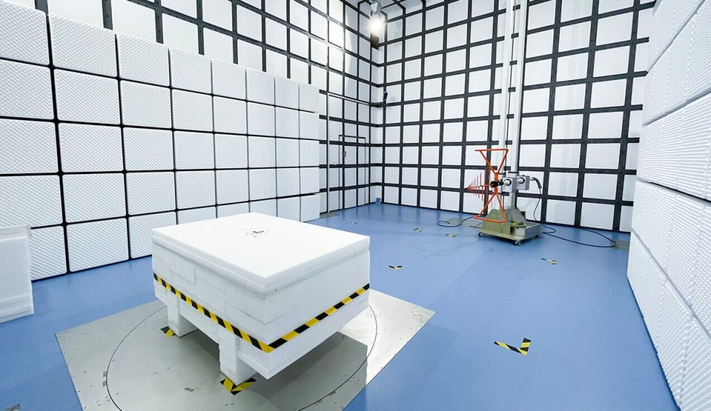
A common EMC antenna mast configuration provides approximately 1 m to 4 m antenna-height adjustment.
The Standard 3m Method Anechoic Chamber includes an antenna tower designed for this height range together with a rotating EUT platform.
During automated testing, the system may:
1. Rotate the EUT to locate a high-emission angle.
2. Move the antenna vertically through the programmed range.
3. Record the height producing the maximum signal.
4. Repeat the measurement in the other antenna polarization.
5. Return to the maximum angle, height, and polarization.
6. Perform the required final detector measurement.
The result is more representative of the actual worst-case emission than a measurement taken at one arbitrary antenna height.
EUT Angle and Antenna Height Must Be Optimized Together
The maximum EUT angle and maximum antenna height are not completely independent.
Changing the EUT angle can change:
* Which cable faces the antenna
* Which enclosure opening is visible
* The effective radiation pattern
* The reflected signal path
This means the antenna height that produces the maximum signal at 20° EUT rotation may not be the same height that produces the maximum at 150°.
For significant emission frequencies, an automated EMC measurement system may therefore search both parameters rather than finding one angle and assuming one fixed antenna height applies to every frequency.
The practical objective is to determine the combination of:
Frequency + EUT Angle + Antenna Height + Polarization
that produces the maximum measured radiated disturbance.
This coordinated search is one of the main reasons automated turntables and antenna masts improve radiated emission measurement repeatability.
Antenna Polarization Is the Third Positioning Variable
Radiated emissions measurements also commonly evaluate both horizontal and vertical antenna polarization.
The strongest polarization depends on the orientation of the radiating structure.
A vertically routed cable may produce stronger coupling to a vertically polarized receiving antenna, while a horizontal PCB structure or enclosure opening may produce a larger reading in horizontal polarization.
Automatic polarization switching allows the measurement sequence to evaluate both conditions without manually removing and rotating the antenna.
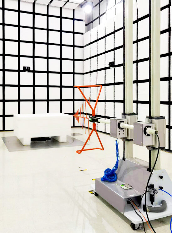
The GEAM-4600 antenna mast system supports antenna height movement together with 0°/90° polarization switching, allowing angle, height, and polarization to be coordinated through the positioning controller.
Why Positioning Matters More Near the Emission Limit
Positioning errors become particularly important when the measured emission is close to the regulatory limit.
Suppose one fixed position gives:
Limit: 40 dBµV/m
Measured level: 37 dBµV/m
The product appears to have a 3 dB margin.
But if EUT rotation or antenna height scanning identifies another position at 42 dBµV/m, the same product actually fails the test.
A measurement result is therefore only meaningful if the required maximization procedure has been completed.
This is also why radiated emissions troubleshooting should record the physical test position. Useful data includes:
* Turntable angle
* Antenna height
* Antenna polarization
* Frequency
* EUT operating mode
* Cable arrangement
Without this information, reproducing a failed emission later can be difficult.
Positioning Errors That Can Change EMC Results
Automatic movement improves repeatability, but the positioning system still needs correct setup.
Common problems include:
EUT Is Not Centered on the Turntable
If the EUT is significantly offset from the rotation center, its antenna distance changes as it rotates.
For large products, part of the EUT may also move outside the validated test volume or quiet zone.
External Cables Move During Rotation
A cable that changes shape as the turntable rotates may change its own radiation characteristics.
Cable routing should remain controlled throughout the complete rotation.
Antenna Height Reference Is Incorrect
The mast position should correspond to the defined antenna reference point rather than simply the physical position of the carriage.
Different antenna mounting brackets can change the actual antenna center height.
Antenna Cable Pulls on the Mast
RF cable weight or tension can change antenna alignment, especially during a 1–4 m vertical scan.
The Turntable Moves Too Quickly
During continuous rotation, the EMI receiver must have enough time to capture narrow angular maxima.
Turntable speed should therefore be coordinated with receiver sweep time, detector behavior, and measurement dwell time.
Semi-Anechoic and Fully Anechoic Chambers Are Different
Antenna height scanning should not be applied mechanically to every EMC chamber configuration.
A standard 3m semi-anechoic chamber uses a conductive ground plane. The reflected signal from that ground plane is one of the reasons vertical antenna scanning is important.
A Fully Anechoic Chamber (FAR) has absorber material on the floor as well as the walls and ceiling.

Because the FAR is designed to suppress the ground reflection, some radiated emission methods can use a fixed receiving antenna height and rely primarily on EUT rotation rather than the same 1–4 m height scan used in a semi-anechoic configuration.
The correct procedure depends on the applicable EMC standard, frequency range, chamber validation method, and product requirement.
This distinction is important when planning an EMC chamber. A 3 m SAC and a 3 m FAR may use the same nominal test distance but require different positioning procedures.
More background on chamber configuration is available in Guidance on Selecting 3M, 5M, and 10M Anechoic Chambers for EMC Testing Applications.
Automated Pre-Scan and Final Measurement
A practical automated radiated emission test does not need to perform the slowest measurement at every angle and every antenna height.
A more efficient sequence is:
Pre-scan: quickly identify significant emission frequencies and approximate maximum positions.
Maximization: search EUT angle, antenna height, and polarization more carefully at selected frequencies.
Final measurement: return to the recorded worst-case position and perform the required final measurement.
Broadband antennas can make this process faster because fewer antenna changes interrupt the positioning sequence. This is discussed in How Broadband Antennas Improve EMC Test Efficiency.
The positioning system should record enough information to reproduce each critical result.
For radiated emission measurements near the compliance limit, the important question is not simply what level was measured. It is whether the laboratory has systematically searched the EUT orientation, receiving antenna position, and polarization that produce the maximum emission required by the applicable test method.