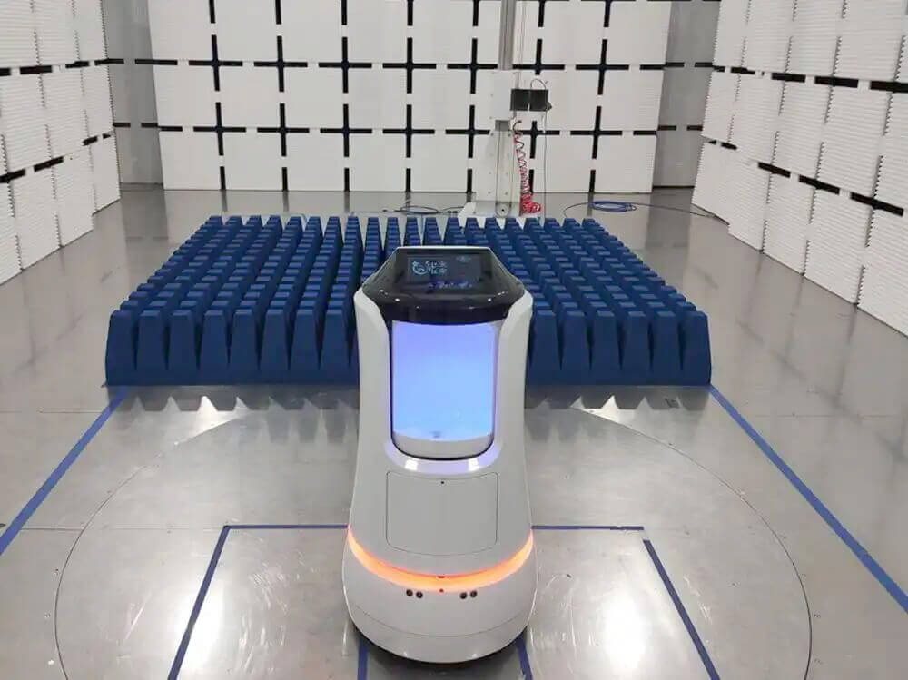
Low-frequency electromagnetic disturbances are often dominated by magnetic fields generated by current flowing through power cables, switching circuits, transformers, motors, lighting equipment, and other electrical conductors.
These disturbances cannot always be evaluated effectively with biconical, log-periodic, or horn antennas. At frequencies from several kilohertz to tens of megahertz, a loop antenna provides a more direct method for measuring the magnetic component of the electromagnetic field.
Loop antennas are commonly used for low-frequency magnetic field measurements, radiated emissions testing, EMI troubleshooting, lighting equipment evaluation, and near-field investigations. Their performance depends on loop size, frequency range, antenna factor, orientation, sensitivity, dynamic range, and the distance between the antenna and the equipment under test.
The available EMC antenna range includes loop antennas together with hybrid, log-periodic, and horn antennas for different EMC measurement bands.
Why Loop Antennas Are Used at Low Frequencies
An electric current produces a magnetic field around the conductor carrying it. At low frequencies and short measurement distances, the electric and magnetic field components may not have the fixed relationship normally assumed in far-field measurements.
This is particularly relevant around:
* AC power cables
* Transformers
* Switching power supplies
* Inductors and coils
* Electric motors
* Lighting control circuits
* Wireless charging systems
* Industrial power equipment
* Automotive wiring harnesses
* High-current busbars
A loop antenna responds mainly to the magnetic flux passing through the loop area. The changing magnetic field induces a voltage at the antenna output, which can then be measured by an EMI receiver, spectrum analyzer, or other suitable instrument.
This makes the loop antenna useful for identifying magnetic field emissions that may be difficult to isolate with an electric-field antenna.
Frequency Range for Low-Frequency Magnetic Field Measurements
Loop antennas used in EMC testing commonly cover frequencies beginning at 9 kHz and extending to 30 MHz.
This range includes disturbances from:
* Power conversion equipment
* Inductive charging systems
* Electronic lighting products
* Switching regulators
* Industrial control equipment
* Household appliances
* Automotive electronics
* Low-frequency communication systems
* Conductive and wireless energy-transfer systems
Below approximately 30 MHz, the measurement setup may be strongly influenced by the distance between the antenna and the source. Cable location, loop orientation, nearby conductive structures, and the dimensions of the EUT can all affect the measured result.
The selected loop antenna must therefore match both the required frequency range and the measurement method specified by the applicable EMC standard.
Active and Passive Loop Antennas
Loop antennas are available in active and passive configurations. Although both respond to magnetic fields, they are suited to different signal levels and measurement conditions.
Active Loop Antennas
An active loop antenna includes a built-in amplifier that increases the output from the loop before the signal reaches the measuring instrument.
This improves sensitivity when measuring weak magnetic field emissions, especially at lower frequencies where the voltage induced in a compact loop may be small.
Active loop antennas are useful for:
* Low-level radiated emissions measurements
* EMI source investigation
* Spectrum monitoring
* Pre-compliance testing
* Measurements with long receiver cables
* Applications requiring a lower system noise floor
The amplifier also introduces operating limits. A strong field may overload the active circuit and produce an inaccurate result. Battery voltage can also affect amplifier gain if the antenna is operated below its specified supply level.
The operator should monitor low-battery and saturation indicators where these are provided.
Passive Loop Antennas
A passive loop antenna does not contain a built-in amplifier. Its output is determined directly by the loop structure, magnetic field strength, frequency, and connected measurement system.
Passive loops are generally less sensitive than active models, but they offer several practical benefits:
* No batteries or external power supply
* Lower risk of amplifier saturation
* Simpler signal path
* Suitable operation in stronger fields
* Ability to handle higher input levels
* Stable operation when used with an external preamplifier
An external low-noise preamplifier may be added when greater receiving sensitivity is required. The preamplifier, cable loss, and loop antenna factor must then be included in the measurement correction data.
Measuring from 9 kHz to 30 MHz
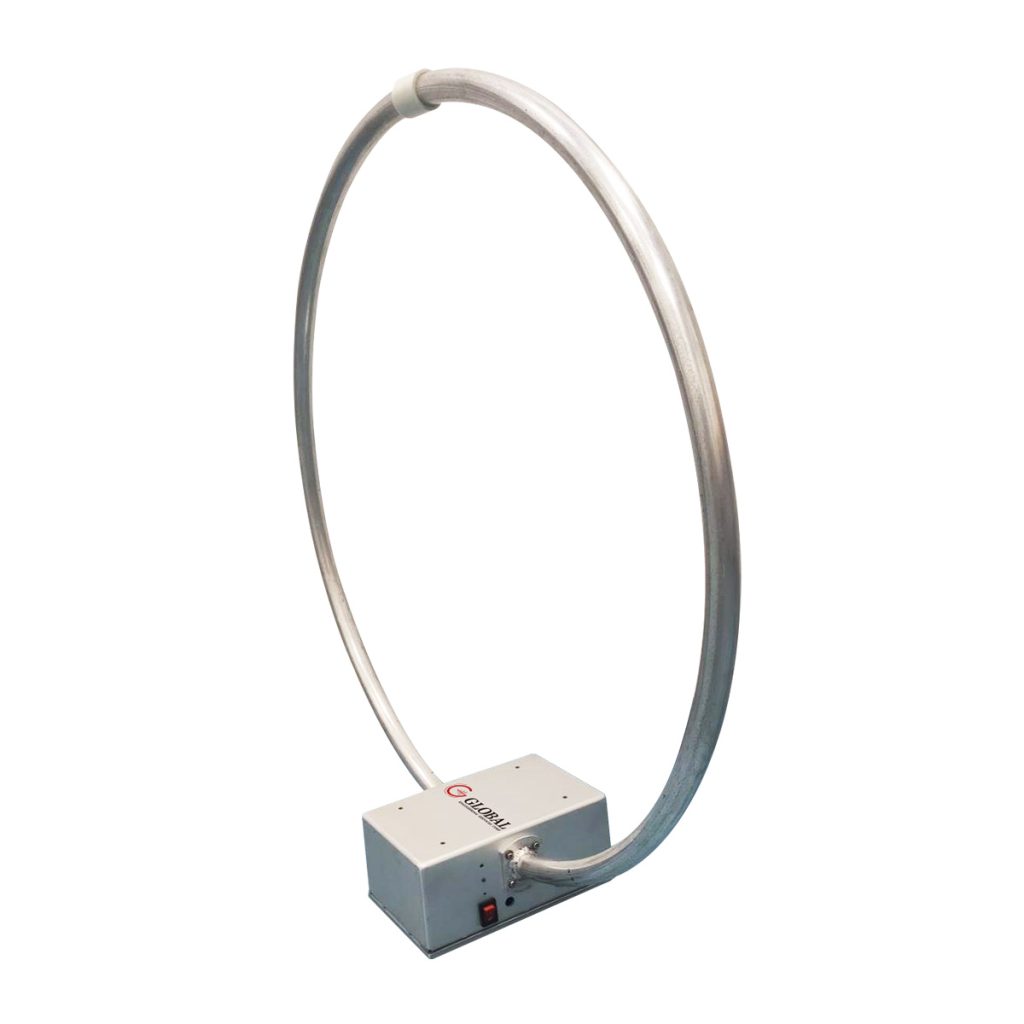
The 1313 Series Loop Antenna provides active and passive configurations for magnetic field measurements from 9 kHz to 30 MHz.
Both versions use a loop diameter of approximately 60 cm and a nominal 50-ohm output through a female BNC connector.
The active 1313-1A model is intended for sensitive receiving applications. Its built-in amplifier provides greater sensitivity across the low-frequency range, while low-battery and saturation indicators help the operator identify conditions that could affect measurement accuracy.
The passive 1313-1P model covers the same 9 kHz to 30 MHz frequency range without an internal amplifier. It is suitable where the signal level is higher, a separate preamplifier is preferred, or the measurement setup requires a passive antenna response.
Selecting between the two versions depends on:
* Expected magnetic field level
* Receiver sensitivity
* Measurement distance
* Required dynamic range
* Risk of active-circuit overload
* Available external preamplification
* Applicable calibration data
A weak signal does not automatically require an active antenna. The complete receiver noise floor and cable loss should be reviewed before the measurement system is configured.
Antenna Orientation and Magnetic Field Direction
Loop antenna orientation has a direct effect on the measured level.
The antenna produces its highest response when the magnetic field passes through the loop area. Rotating the loop changes its coupling to the field and can reveal the direction of the dominant magnetic field component.
During a measurement, the loop may need to be tested in several orientations to find the maximum reading.
This is important because magnetic emissions from a product may come from different sources and directions. A transformer may generate one field orientation, while an external cable or internal current loop produces another.
For repeatable results, the test report should record:
* Loop orientation
* Distance from the EUT
* Antenna height
* Position relative to the EUT
* EUT operating mode
* Cable arrangement
* Measured frequency
* Applied antenna-factor correction
A change in orientation or distance can produce a large change in measured field strength, particularly during near-field measurements.
Measurement Distance and Near-Field Effects
Low-frequency magnetic field measurements are often performed close to the source.
In this region, magnetic field strength can decrease rapidly as the antenna moves away from the EUT. A difference of only several centimeters may significantly change the measured result.
For this reason, measurements used for compliance testing must follow the distance and positioning requirements of the applicable standard.
For troubleshooting measurements, a loop antenna can be moved around the EUT to locate areas of strong magnetic field leakage. Typical sources include:
* Transformer cores
* Switching inductors
* Power input cables
* Motor drive circuits
* Enclosure openings
* Printed circuit board current loops
* Grounding connections
* High-current connectors
Once the source area has been identified, a smaller near-field probe may be used for more detailed localization at component or PCB level.
A calibrated EMC loop antenna is better suited to repeatable field measurements, while a small probe is usually more useful for locating the source of an interference problem.
Triple Loop Antennas for Lighting Equipment
Some low-frequency radiated disturbance measurements require a large loop antenna system surrounding the equipment under test.
The 1313-S3-2M Triple Loop Antenna is designed for magnetic field disturbance measurements from 9 kHz to 30 MHz according to the loop antenna system described in CISPR 16-1-4.
The structure consists of three mutually perpendicular loop antennas, each with a diameter of two meters. The EUT is positioned near the center of the system.
The three perpendicular loops measure magnetic field components in different directions without requiring the complete structure or EUT to be rotated for each orientation.
This arrangement is primarily used for radiated disturbance measurements from:
* LED lighting equipment
* Electronic ballasts
* Fluorescent lighting systems
* Lighting control devices
* Dimmers
* Luminaires
* Similar electrical equipment covered by CISPR 15
The outputs from the three loops are connected to the measuring receiver through the corresponding current-to-voltage probes and BNC connections.
The large loop dimensions and fixed geometry provide a more repeatable setup than moving a small loop manually around the product.
Loop Antenna Calibration and Correction Data
A loop antenna does not directly display magnetic field strength. The voltage measured by the receiver must be converted using the calibrated antenna factor or transducer factor.
The correction process may include:
* Receiver reading
* Loop antenna factor
* RF cable loss
* Preamplifier gain
* Probe or transducer correction
* Measurement-system uncertainty
The calibration data must cover the required frequency range and correspond to the individual antenna where possible.
For an active loop antenna, calibration depends on the performance of both the loop and its internal amplifier. Low battery voltage, amplifier saturation, output mismatch, or poor BNC cable contact can change the measured response.
Before testing, check that:
* The active antenna battery is fully charged.
* The saturation indicator is not active.
* The BNC connector is secure.
* The correct calibration file is loaded.
* The receiver input is properly terminated.
* Cable-loss correction matches the cable in use.
* Nearby equipment is not creating additional magnetic fields.
Avoiding Saturation and Receiver Overload
A strong magnetic field can overload an active loop antenna or the connected EMI receiver.
When saturation occurs, the measured value may stop increasing in proportion to the actual field. The result can appear stable even though it is no longer accurate.
Possible corrective actions include:
* Increasing the distance from the source
* Using a passive loop antenna
* Adding attenuation
* Reducing external preamplifier gain
* Selecting a higher receiver input range
* Checking whether the disturbance is generated by the EUT or test equipment
Receiver overload may also be caused by strong signals outside the frequency being investigated. Filtering can be useful where a high-level low-frequency signal prevents accurate measurement of weaker signals elsewhere in the band.
Environmental Noise During Magnetic Field Measurements
Low-frequency magnetic field measurements are particularly sensitive to the surrounding electrical environment.
Background signals may come from:
* Building power cables
* Lighting systems
* Nearby transformers
* Electric motors
* Elevators
* Laboratory power supplies
* Computer monitors
* Wireless charging devices
* Test equipment
* Grounding conductors
A background measurement should be performed with the EUT switched off while the antenna, receiver, cables, and laboratory equipment remain in the same positions.
If the background level is close to the measured EUT emission, the result may not represent the product accurately.
Testing inside a suitable shielded room can reduce external electric-field interference, but ordinary shielding does not always provide strong attenuation of very low-frequency magnetic fields. The test location and nearby current-carrying conductors still require attention.
Magnetic Field Measurement and Immunity Testing Are Different
A receiving loop antenna measures magnetic field emissions produced by the EUT. A magnetic field immunity system performs the opposite function: it generates a controlled field and exposes the EUT to that field.
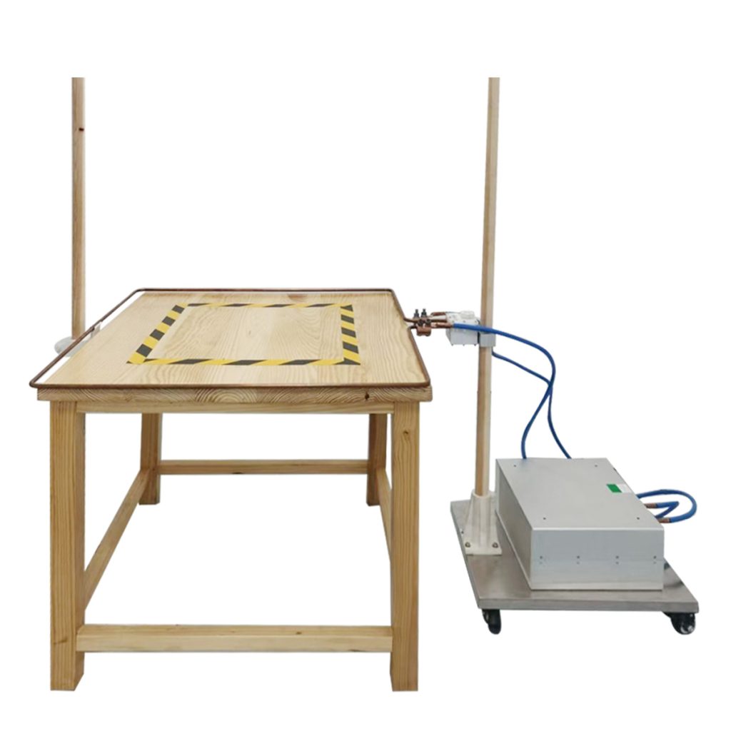
The Power Frequency Magnetic Field Test System 1313-S1-120AT-1M is intended for AC magnetic field immunity tests such as IEC 61000-4-8.
It uses a one-meter square coil and current transformer to generate a magnetic field around the EUT. The system can produce field strengths up to approximately 110 A/m and can be positioned for horizontal or vertical testing.
This equipment should not be confused with a measurement loop antenna:
* A measurement loop receives magnetic field disturbances.
* A power-frequency coil generates a specified magnetic field.
* The receiving system uses antenna-factor corrections.
* The immunity system uses field calibration and controlled coil current.
Some laboratories require both systems because emissions and immunity testing address different aspects of electromagnetic compatibility.
Selecting a Loop Antenna
Before selecting a loop antenna for low-frequency magnetic field measurements, confirm:
* Required frequency range
* Applicable EMC standard
* Expected magnetic field level
* Active or passive operation
* Antenna sensitivity
* Dynamic range
* Risk of saturation
* Loop diameter
* Measurement distance
* Antenna-factor calibration
* Connector type
* Receiver input impedance
* Cable-loss correction
* Required loop orientation
* Single-loop or triple-loop configuration
A compact active or passive loop is suitable for general magnetic field measurement, pre-compliance testing, and EMI troubleshooting. A calibrated triple loop antenna system is more appropriate when the applicable standard requires measurements around lighting equipment or similar products within a defined large-loop structure.