
Anechoic Chamber Introduction
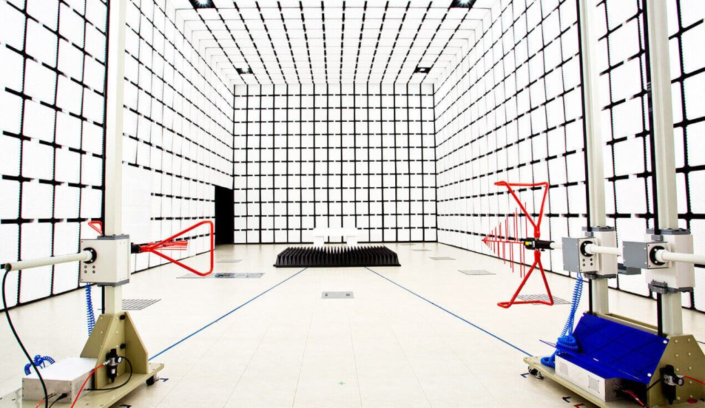
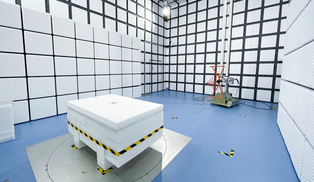
The standard 5m method anechoic chamber (5m SAC) is primarily designed for electromagnetic compatibility (EMC) testing of larger equipment under test (EUT), including radiated emissions (RE) and radiated susceptibility (RS) tests. Below are its typical technical parameters and design requirements:
Key Structural Parameters
| Test Distance | 5m (distance from EUT to receiving antenna) |
|---|---|
| Frequency Range | Standard Testing: 30 MHz ~ 18 GHz (extendable to 40 GHz with high-frequency absorbers) Low-Frequency Testing: Supports below 1 GHz (requires optimized absorbers and shielding design) |
| Shielding Effectiveness | Low Frequency (14 kHz ~ 1 MHz): ≥ 80 dB High Frequency (1 MHz ~ 18 GHz): ≥ 100 dB Extreme Frequencies (e.g., 40 GHz): ≥ 60 dB (requires special absorbers) |
| Grounding Resistance | Standard: IEC 60364-6 (GB/T 16895.23) Requirement: ≤ 4Ω |
| Insulation Resistance | Standard: IEC 60364-6 (GB/T 16895.23) Requirement: ≤ 2 MΩ |
| Quiet Zone | Effective Test Area Diameter/Height: 2~3m (depends on chamber size and absorber performance) |
| Grounding Resistance | Standard: IEC 60364-6 (GB/T 16895.23) Requirement: ≤ 4Ω |
| Insulation Resistance | Standard: IEC 60364-6 (GB/T 16895.23) Requirement: ≤ 2 MΩ |
| Field Uniformity | ≤ 6 dB variation within a 3m×3m area (compliant with IEC 61000-4-3 for RS testing) |
| Influence Assessment of Radiated Emission Test Table | Compliance Standards: CISPR 16-1-4, ANSI C63.4 Requirement: The influence assessment results of the radiated emission test table must be incorporated into the uncertainty evaluation of radiated emission measurements |
| Ambient Noise Level | At least 6 dB below the EMC product standard limits |
Structural Design Parameters
| Chamber Dimensions | Length: Typically 12~15m (meets test distance and quiet zone requirements) Width: 8~10m (ensures quiet zone integrity) Height: 6~8m (accommodates antenna movement and quiet zone) |
|---|---|
| Absorbing Materials | Type: High Frequency: Pyramidal carbon foam absorbers; Hybrid (Low Frequency): Ferrite tiles + pyramidal absorbers Low-Frequency Performance: Ferrite tiles (30 MHz ~ 1 GHz) High-Frequency Performance: Pyramidal absorbers (>1 GHz, typical height 0.3~0.6m) |
| Shielding Structure | Material: Welded galvanized steel or copper plates with conductive gasket seals at joints Shielded Door: Hermetic design with RF-filtered access system |
| Turntable & Antenna System | Turntable Diameter: 2~3m, load capacity ≥ 1~5 tons Antenna Polarization: Supports automatic horizontal/vertical switching Antenna Tower: Adjustable height range of 1~5m |
Compliance Standards
| EMC Testing Standards | Radiated Emissions: CISPR 16-2-3 Radiated Susceptibility: IEC 61000-4-3 Automotive Electronics: ISO 11451/11452 Military/Aerospace: MIL-STD-461/DO-160 |
|---|---|
| Site Validation | NSA: Complies with CISPR 16-1-4 SVSWR: ≤ 6 dB (30 MHz ~ 18 GHz) |
Typical Applications
| Radiated emissions (RE) testing for electronics | |
|---|---|
| Radiated susceptibility (RS) testing | |
| Antenna pattern measurements | |
| EMC certification for automotive electronics, military equipment, and medical devices |