RF leakage in an EMC shielded room usually occurs where the conductive shielding boundary is interrupted. The most common locations are RF shielded doors, panel joints, power-line filters, cable penetrations, and ventilation openings.
A shielded room may appear mechanically intact while allowing external radio-frequency signals to enter or internally generated signals to escape. Even a small discontinuity in a conductive joint can reduce shielding effectiveness at certain frequencies.
Finding the source requires more than visual inspection. Engineers must distinguish actual shielding leakage from interference generated inside the room, then use controlled RF measurements to locate and verify the affected area.

What Causes RF Leakage in a Shielded Room?
An electromagnetic shielded chamber relies on a continuous conductive enclosure to attenuate electromagnetic fields.
Metal panels provide the main shielding structure, but every door, cable, ventilation opening, and service connection introduces a potential weakness.
Common RF leakage sources include:
| Location | Typical Problem | What to Check |
|---|---|---|
| Shielded door | Worn fingerstock or uneven contact pressure | Door perimeter and gasket condition |
| Panel joints | Loose fasteners, corrosion, damaged conductive joints | Seams and panel connections |
| Power filters | Poor mounting contact or unsuitable replacement | Filter housing and shield-wall interface |
| Cable penetrations | Unfiltered cables or improper connector installation | Feedthrough and cable entry panels |
| Ventilation | Damaged honeycomb or poor perimeter bonding | Ventilation waveguide assembly |
| Structural modifications | New holes or improperly sealed openings | Recently modified areas |
The source of RF leakage is often a localized defect rather than a failure of the entire shielding enclosure.
RF Leakage Around Shielded Doors
Shielded doors are among the most common locations where shielding performance deteriorates.
Unlike fixed wall panels, doors are opened and closed repeatedly. Their conductive contacts must maintain reliable electrical continuity throughout the entire perimeter.
Common problems include:
– Bent or broken conductive fingerstock
– Worn RF gaskets
– Dirt or oxidation on contact surfaces
– Incorrect door alignment
– Uneven compression
– Damaged threshold contacts
A door may close and lock normally while still having insufficient electrical contact along one edge.
How to find the leakage: Inspect the complete door perimeter, particularly corners, hinges, and lower thresholds. During a controlled RF leakage survey, compare received signal levels around these locations.
A localized increase in the test signal near one section of the door may indicate a shielding discontinuity.
Leakage Through Panel Joints and Seams
Modular shielded rooms use conductive connections between metal panels.
These joints must remain electrically continuous despite building movement, temperature variation, and mechanical stress.
Potential problems include loose fasteners, corrosion, damaged joint materials, and gaps introduced during renovation.
A small gap can behave differently across frequency. A joint may provide adequate attenuation at one frequency but become a significant leakage path at a higher frequency.
How to find the leakage: Examine accessible panel seams and corners, particularly where structural changes or impacts have occurred.
A localized RF scan can help identify the affected section before panels are dismantled.
Repairs must restore the shielding continuity specified by the original enclosure design.
RF Leakage Through Filters and Cable Penetrations
Electrical power and communication signals must cross the shielded enclosure without creating uncontrolled RF paths.
Power-line filters, filtered feedthroughs, shielded connectors, and properly installed penetration panels are used for this purpose.
Leakage may occur when:
– A filter mounting flange loses conductive contact.
– A replacement filter has inadequate RF attenuation.
– An unfiltered cable passes through the enclosure.
– A penetration-panel gasket becomes damaged.
– Cable shielding is terminated incorrectly.
– An unused opening is not properly closed.
A common problem is adding new equipment without reviewing its connections to the shielding boundary.
For example, routing an ordinary Ethernet cable through an unprotected opening can compromise an otherwise effective shielded room.
How to find the leakage: Review all cables crossing the enclosure, then inspect associated feedthroughs, filters, and mounting interfaces.
Electrical testing alone cannot establish RF shielding performance. Suspected defects require suitable RF verification.
RF Leakage at Ventilation Openings
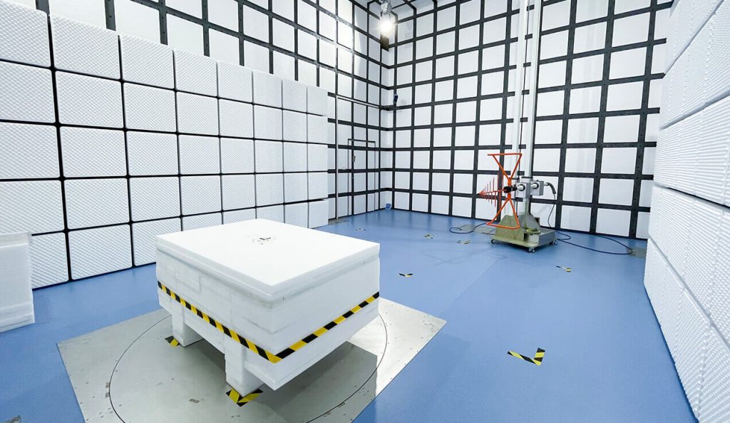
Ventilation openings allow air to circulate through an EMC shielded room.
To maintain RF attenuation, these openings commonly use honeycomb waveguide-below-cutoff structures.
Shielding performance can deteriorate because of:
– Damaged honeycomb cells
– Corrosion
– Poor mounting contact
– Incorrect replacement panels
– Unsealed gaps around the ventilation assembly
A ventilation panel may continue providing adequate airflow while its shielding performance has been reduced.
How to find the leakage: Inspect the honeycomb structure and its conductive mounting perimeter. Include the ventilation area in the RF leakage survey, especially after HVAC modification or panel replacement.
For the construction and function of these components, see Main Components of a Semi-Anechoic Chamber.
How to Distinguish RF Leakage from Internal EMI
Unexpected RF signals inside a shielded room do not automatically prove that the enclosure is leaking.
The interference may originate from equipment already installed inside the room.
Possible internal sources include:
– Switching power supplies
– LED lighting drivers
– Cameras
– Motor controllers
– Computers
– Monitoring equipment
– Communication interfaces
A useful first step is to perform a background RF measurement with the EUT removed or switched off, where the test setup permits.
If a suspicious signal disappears when a particular internal device is turned off, that device should be investigated before assuming the shielded enclosure has failed.
If the signal remains, compare its frequency and behavior with known external RF sources and previous chamber background measurements.
This helps separate an internal EMI noise problem from a genuine shielding-effectiveness problem.
How to Locate RF Leakage Using Test Equipment
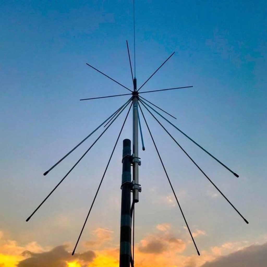
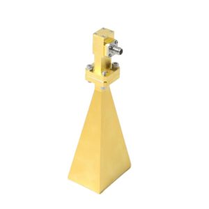
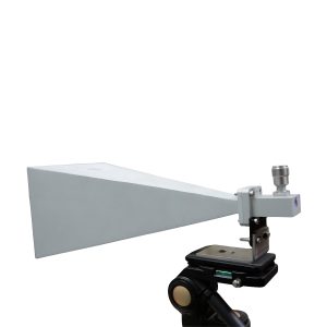
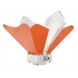
A controlled RF leakage survey can use:
– RF signal generator
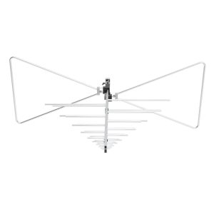
– Transmitting antenna
– Receiving antenna or suitable field probe
– Spectrum analyzer or EMI receiver
– RF measurement cables
– Measurement records
A common diagnostic arrangement places a known RF source on one side of the shielding boundary and the receiving equipment on the other.
The measurement team then examines potential leakage locations using consistent test conditions.
A practical troubleshooting procedure includes five steps.
Step 1: Establish a Reference
Verify the RF source, receiving instrument, antennas, and cables. Record an appropriate reference measurement using the selected procedure.
Step 2: Inspect High-Risk Locations
Begin with shielded doors, panel joints, penetration panels, filters, and ventilation openings.
Step 3: Scan Suspected Leakage Areas
Move the receiving probe or antenna through defined positions while maintaining consistent source level, frequency, orientation, and measurement geometry.
Step 4: Identify Localized Signal Increases
A repeatable increase in received signal near a particular joint or opening may indicate a leakage path.
Step 5: Confirm the Suspected Defect
Repeat the measurement and check for instrument, cable, or ambient-signal pickup.
A diagnostic leakage survey helps locate defects but should not be confused with a formal shielding effectiveness acceptance test.
Measuring Shielding Effectiveness
Shielding effectiveness (SE) is expressed in decibels and describes how much an enclosure attenuates electromagnetic energy.
For a defined electric-field measurement arrangement:
SE (dB) = 20 log₁₀(Ereference / Eshielded)
The reference and shielded measurements must follow a consistent, appropriate test method.
For example, 80 dB attenuation corresponds to an electric-field amplitude reduction by a factor of 10,000.
However, one measurement at one frequency cannot establish shielding performance across the complete operating range.
IEEE 299-based methods provide established procedures for measuring large electromagnetic shielding enclosures.
The required test frequencies, measurement locations, antenna configurations, and acceptance limits should follow the applicable project specification.
Why RF Leakage Varies with Frequency
RF leakage is frequency-dependent.
At lower frequencies, shielding behavior may be strongly influenced by magnetic-field coupling, conductive continuity, and material properties.
At higher frequencies, relatively small openings, seams, and improperly terminated connections can become significant leakage paths.
The dimensions and geometry of an aperture influence how electromagnetic energy couples through it.
As a result, a room may achieve acceptable shielding at 100 MHz but show reduced attenuation at several gigahertz.
This does not necessarily indicate inadequate shielding material.
The weakness may be concentrated around a door contact, penetration, or ventilation interface.
Testing at multiple relevant frequencies is therefore important when identifying shielding defects.
Repairing RF Leakage Points
Corrective action depends on the location and cause of the defect.
| Identified Problem | Typical Corrective Action |
|---|---|
| Worn door contact | Replace the specified contact or gasket |
| Poor door alignment | Adjust mechanical compression and alignment |
| Damaged panel seam | Restore the approved conductive joint |
| Filter mounting gap | Correct the conductive mounting interface |
| Unfiltered cable | Install a suitable filtered or shielded feedthrough |
| Damaged ventilation panel | Repair or replace the specified waveguide assembly |
Repairs should preserve the original shielding design.
Ordinary sealants, tapes, gaskets, and replacement parts should not be assumed to provide adequate RF shielding without appropriate specifications.
After repair, repeat the diagnostic measurement at the original problem location under comparable conditions.
Major structural repairs may require broader shielding effectiveness verification before returning the room to compliance testing.
For preventive maintenance practices, see How to Maintain EMC Shielded Rooms for Long-Term Performance.
When to Repeat Shielding Effectiveness Testing
A shielding effectiveness assessment is particularly useful after:
– RF door replacement or major adjustment
– Power-filter replacement
– New cable or pipe penetrations
– Ventilation-system modification
– Shielding panel repairs
– Building renovation affecting the enclosure
– Unexplained increases in chamber background RF noise
For an anechoic chamber, shielding effectiveness testing must also be distinguished from NSA, SVSWR, and field-uniformity validation.
These measurements evaluate different electromagnetic characteristics of the chamber.
Passing a shielding test does not automatically confirm satisfactory radiated emissions site performance or radiated immunity field uniformity.
A complete acceptance process should address the parameters relevant to the intended applications, as described in From Site Planning to Validation: A Complete Guide to EMC Chamber Projects.
RF Leakage Troubleshooting Checklist
When RF leakage is suspected, follow this sequence:
1. Identify the signal source: Determine whether the unwanted RF signal originates inside or outside the room.
2. Review recent changes: Check equipment installations, cable modifications, and enclosure repairs.
3. Inspect RF doors: Examine contacts, gaskets, alignment, and compression.
4. Check panel joints: Look for corrosion, loose connections, and visible gaps.
5. Inspect penetrations: Review power filters, feedthroughs, and ventilation interfaces.
6. Perform an RF leakage survey: Use controlled test signals and appropriate measurement equipment.
7. Record the defect: Document frequency, location, signal level, and measurement configuration.
8. Repair the affected area: Use suitable shielding components and approved procedures.
9. Verify the repair: Repeat measurements under comparable conditions.
10. Confirm return to service: Complete the required shielding effectiveness verification before resuming affected EMC testing.
The purpose of this process is to identify and repair the actual leakage path rather than replace large sections of the enclosure without measurement evidence.