
Anechoic Chamber Introduction
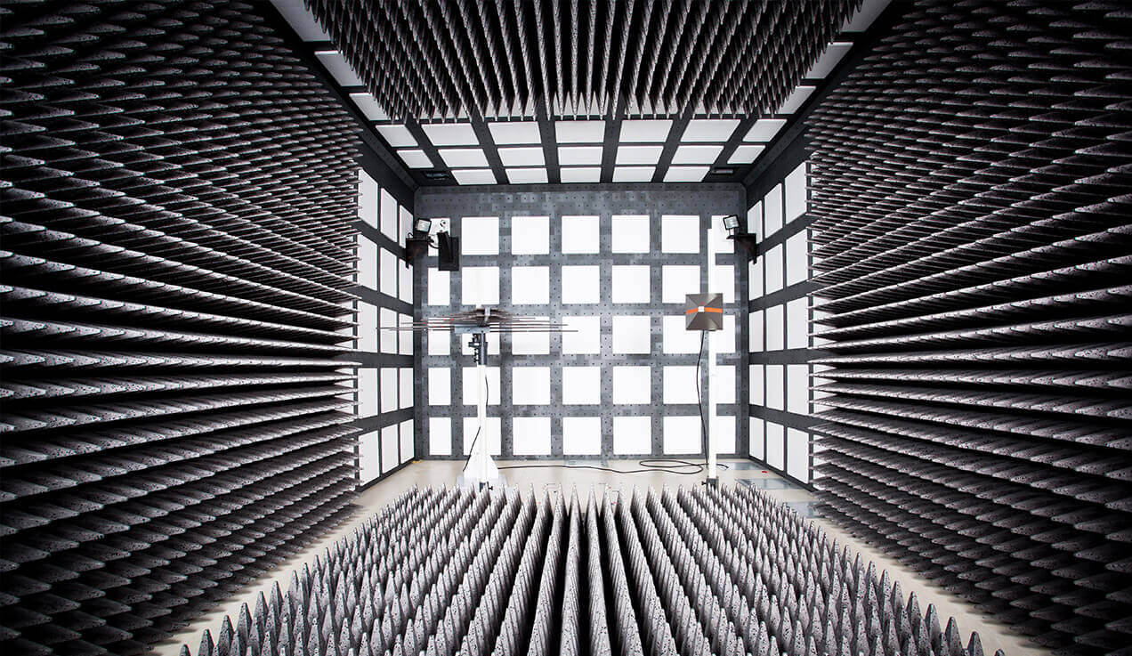
The fully anechoic chamber (FAR) simplifies radiated emission (RE) and radiated spurious emission (RSE) testing by requiring only turntable rotation (without antenna height adjustment as in semi-anechoic chambers), making it ideal for high-efficiency EMC testing applications. Key technical specifications and design requirements are as follows:
Key Test Parameters
| Test Distance | 3m or 5m (EUT to receiving antenna distance) |
|---|---|
| Frequency range | Standard testing: 30 MHz ~ 40 GHz (extendable to millimeter wave bands with customized absorbers) Low-frequency testing: Supports 150 kHz ~ 1 GHz (requires ferrite + pyramidal absorber combination) |
| Shielding effectiveness | Low frequency (14 kHz ~ 1 MHz): ≥ 80 dB High frequency (1 MHz ~ 40 GHz): ≥ 100 dB |
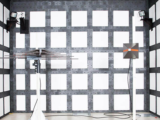
| Quiet zone | Effective test area diameter/height: 0.8m~2.5m (selectable based on sample size) |
| Reference Site Attenuation (for FAR with <5m test distance) | Compliance standards: CISPR 16-1-4 (GB/T 6113.104), ANSI C63.4 Deviation: Within ±4 dB (30 MHz–1 GHz) |
| Normalized Site Attenuation (for FAR with ≥5m test distance) | Compliance Standards: CISPR 16-1-4 (GB/T 6113.104), ANSI C63.4 Deviation: Within ±4 dB (30 MHz–1 GHz) |
| Site Voltage Standing Wave Ratio (SVSWR) | Compliance Standards: CISPR 16-1-4 (GB/T 6113.104), ANSI C63.4 Requirement: ≤ 6 dB |
| Influence Assessment of Radiated Emission Test Table | Compliance Standards: CISPR 16-1-4, ANSI C63.4 Requirement: The influence assessment results of the radiated emission test table must be incorporated into the uncertainty evaluation of radiated emission measurements |
| Ambient noise level | At least 6 dB below test limits |
Structural Design Parameters
| Chamber Dimensions | 3m method FAR typical shielded enclosure:Length: 8.8m (meets test distance and quiet zone requirements) Width: 4.6m (ensures quiet zone integrity) Height: 4.2m (accommodates quiet zone needs) 5m method FAR typical shielded enclosure:Length: 11.8m Width: 7.6m Height: 7.2m (supports large antenna movement and quiet zone) |
|---|---|
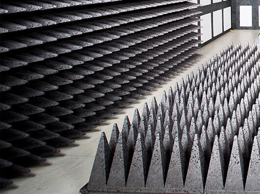
| Absorbing Materials | Type:Ferrite tiles (30 MHz ~ 1 GHz) + carbon-based pyramidal absorbers (1 GHz ~ 40 GHz) Low-frequency optimization: Double-layer ferrite + pyramidal composite structure High-frequency optimization: Absorber height 0.3~0.6m (reduces reflection, improves mmWave performance) |
| Shielding Structure | Material: Double-layer copper or galvanized steel plates welded, with metal conductive adhesive + beryllium copper finger gaskets at joints Shielded door: Hydraulically-driven hermetic door with integrated RF filtering and EMC sealing |
| Turntable and antenna system | Turntable diameter: 1~2.5m, load capacity ≥ 0.5~2 tons Antenna polarization: Automatic horizontal/vertical switching Antenna tower: Height-adjustable |
Compliance Standards
| EMC testing standards | CISPR 32 (GB/T 9254.1 multimedia equipment) ETSI EN 301 489-1/17/52 (EMC requirements for wireless devices like Bluetooth headsets, routers, smartphones, tablets) |
|---|---|
| Site validation | NSA (Normalized Site Attenuation) error ≤ ±4 dB (30 MHz ~ 18 GHz) SVSWR (Site VSWR) ≤ 4 dB (30 MHz ~ 40 GHz) |
Typical Applications
| Radiated emissions testing for laptops and peripherals | |
|---|---|
| Radiated emissions and spurious emissions testing for wireless devices (Bluetooth headsets, routers, smartphones, tablets) |


