The standard 10m method anechoic chamber is designed for higher precision EMC testing or larger equipment, with the following typical technical parameters and design requirements:
| Test Distance | 10m (distance from EUT to receiving antenna) |
|---|---|
| Frequency range | Standard testing: 30 MHz ~ 40 GHz (extendable to millimeter wave bands with customized absorbers) Low-frequency testing: Supports 150 kHz ~ 1 GHz (requires ferrite + pyramidal absorber combination) |
| Shielding effectiveness | Low frequency (14 kHz ~ 1 MHz): ≥ 90 dB High frequency (1 MHz ~ 40 GHz): ≥ 120 dB Extreme bands (e.g., 100 GHz): ≥ 70 dB (requires special high-frequency absorbers) |
| Quiet zone | Effective test area diameter/height: 3~5m (larger quiet zone suitable for big equipment testing) |
| Grounding Resistance | Standard: IEC 60364-6 (GB/T 16895.23) Requirement: ≤ 4Ω |
| Insulation Resistance | Standard: IEC 60364-6 (GB/T 16895.23) Requirement: ≤ 2 MΩ |
| Field uniformity | ≤ ±3 dB variation within 4m×4m area (compliant with IEC 61000-4-3) |
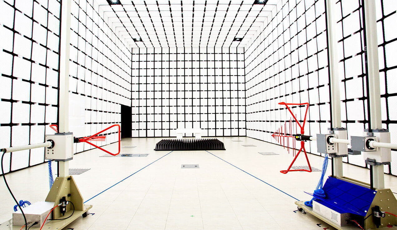
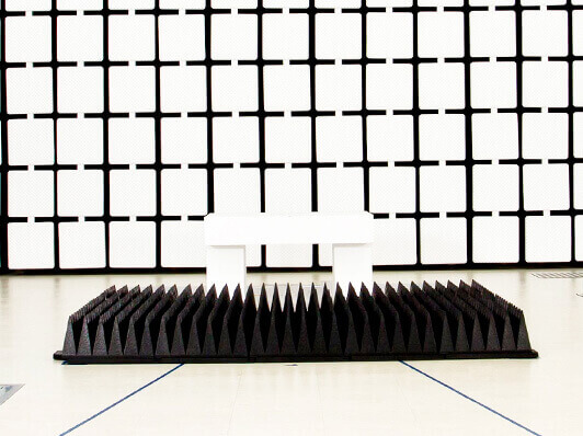
| Influence Assessment of Radiated Emission Test Table | Compliance Standards: CISPR 16-1-4, ANSI C63.4 Requirement: The influence assessment results of the radiated emission test table must be incorporated into the uncertainty evaluation of radiated emission measurements |
| Ambient noise level | At least 10 dB below test limits (higher sensitivity for weak signal detection) |
| Chamber Dimensions | Length: 20~25m (meets test distance and quiet zone requirements) Width: 12~15m (ensures quiet zone integrity) Height: 10~12m (accommodates large antenna movement and quiet zone) |
|---|---|
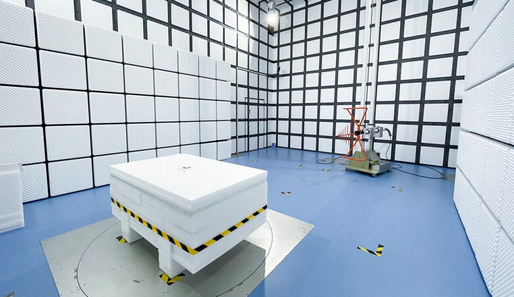
| Absorbing Materials | Type:Ferrite tiles (30 MHz ~ 1 GHz) + carbon-based pyramidal absorbers (1 GHz ~ 40 GHz) Low-frequency optimization: Double-layer ferrite + pyramidal composite structure (enhances low-frequency absorption) High-frequency optimization: Absorber height 2~3m (reduces reflection, improves mmWave performance) |
| Shielding Structure | Material: Double-layer copper or galvanized steel plates welded, with metal conductive adhesive + beryllium copper finger gaskets at joints Shielded door: Hydraulically-driven hermetic door with integrated RF filtering and EMC sealing |
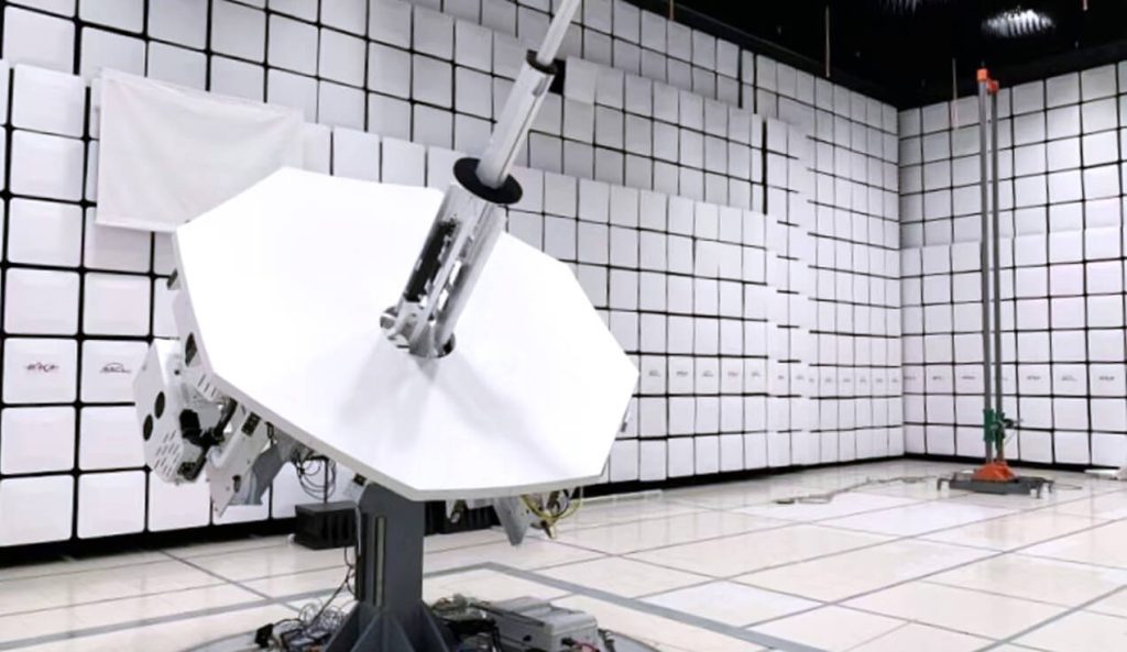
| Turntable and antenna system | Turntable diameter: 3~5m, load capacity ≥ 3~5 tons (supports complete vehicle testing) Antenna polarization: Fully automated multi-axis control (horizontal/vertical/circular) Antenna tower: Adjustable height range 2~8m (meets far-field testing requirements) |
| EMC testing standards | CISPR 25 (GB/T 18655 vehicle electronics radiated emissions) CISPR 32/35 (GB/T 9254.1/2 multimedia equipment) ISO 11451-2 (vehicle electronics radiated immunity) MIL-STD-461G (GJB 151C military equipment) |
|---|
| Power supply and filtering | Power: Three-phase independent filtered system (single/three-phase optional), harmonic suppression ≥ 40 dB
Fiber optic transmission: Signals penetrate chamber via fiber (avoids cable-induced interference) |
|---|---|
| Environmental control | Temperature: 18~25℃ (±1℃ precision control for high-accuracy testing) Humidity: 20%~60% RH (prevents static and absorber aging) |
| Safety systems | IR monitoring + emergency exhaust system (prevents overheating/gas leakage) Full-band RF radiation monitor (real-time display of EM leakage) |
| Radiated emissions/immunity testing for complete vehicles and components | |
|---|---|
| High-frequency EMC testing for aerospace equipment (e.g., avionics) | |
| mmWave band (24~40 GHz) certification for 5G/6G communication devices | |
| EMC testing for large industrial equipment (e.g., wind power converters, high-speed rail electronics) |